
a bearing

A bearing and body technology, applied in the field of connectors, can solve the problems of difficult installation, reduced stability, and large number of bearing installations, and achieve the effect of improving installation firmness and stability

Active Publication Date: 2020-06-16
温州天纳福汽车轴承股份有限公司
View PDF4 Cites 1 Cited by
  • Summary
  • Abstract
  • Description
  • Claims
  • Application Information

AI Technical Summary

Problems solved by technology

[0003] When using bearings to fix the long shaft, due to the large span of the shaft body, it is easy to deform and vibrate during the rotation of the long shaft, which reduces the stability and affects the normal effect of the work. In order to improve this problem , you can use bearings on the long shaft for multi-point support
[0004] At present, when performing the above operations, it is necessary to install multiple bearings in stages. Since most of the bearings and the shaft body are interference fit, they need to be installed by shrink fit or press-in method, which is difficult to install and the installation time is limited. Therefore, the operation requirements for the staff are very high, and according to the actual size of the long shaft, the number of bearings to be used is also different. When the shaft body is long, the number of bearings installed is large, which further increases the difficulty of the staff's operation.
In addition, when lubricating the long shaft after multi-point support, it is difficult for the staff to ensure the uniformity of lubrication at the support, resulting in local wear or rust on the shaft body

Method used


Image

  • a bearing
  • a bearing
  • a bearing

Examples


Embodiment Construction

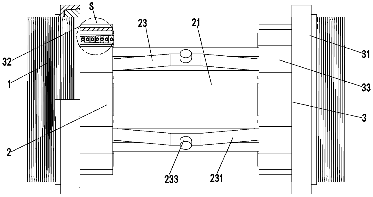
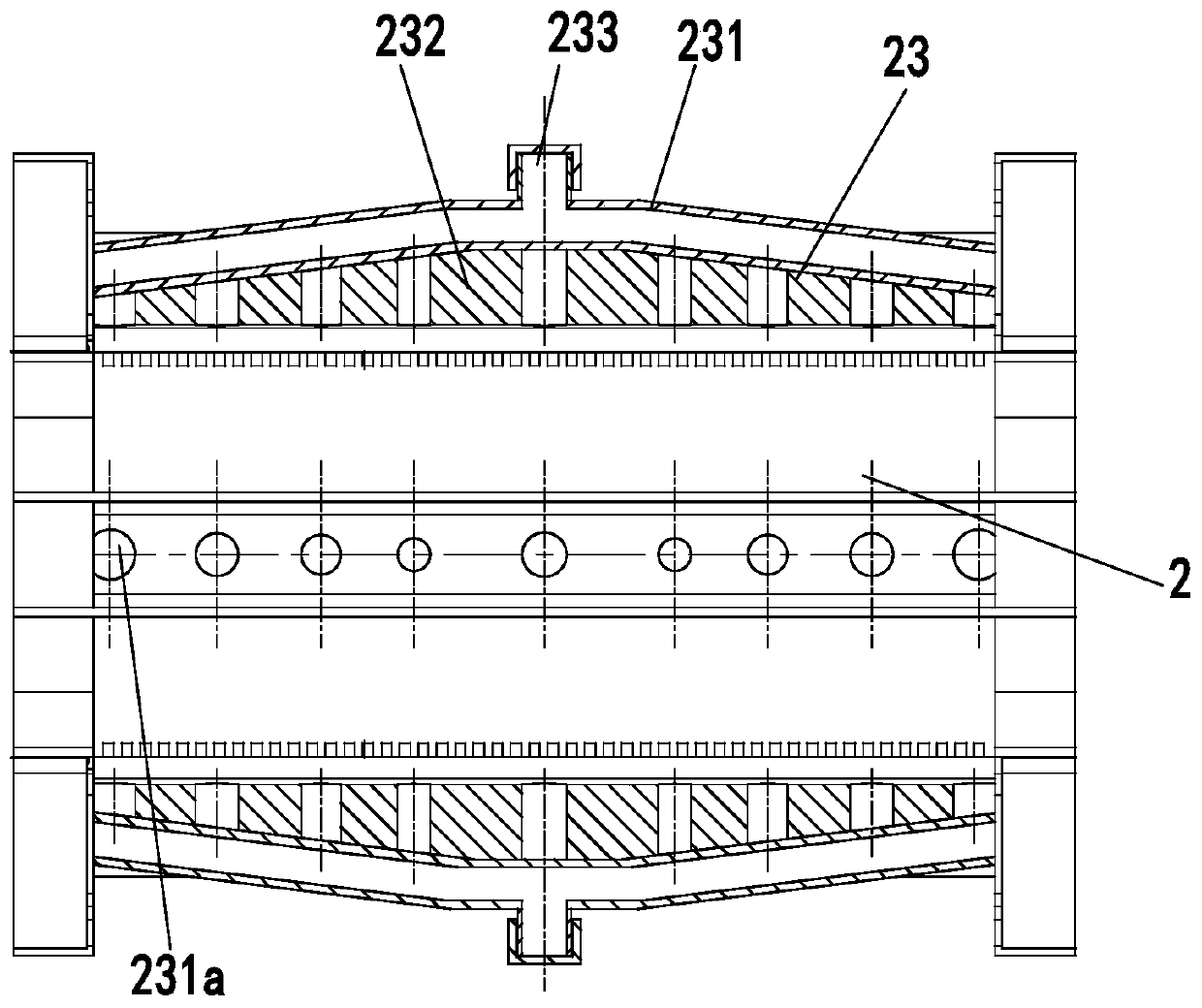
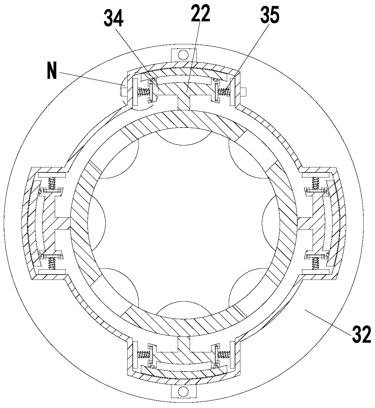
[0027] In order to make the technical means realized by the present invention, creative features, goals and effects easy to understand, the following combination Figure 1 to Figure 5 , to further elaborate the present invention.

[0028] A bearing, comprising a bearing body 1, a spacer 2 and a connecting mechanism 3, the outer wall of the bearing body 1 is provided with threads, and the number of the bearing bodies 1 is two, and a spacer is installed between the two bearing bodies 1 through the connecting mechanism 3 Set 2; of which:

[0029] The spacer 2 includes a sleeve body 21, a clamping block 22 and a lubricating frame 23. The sleeve body 21 is a hollow cylinder structure, and the left and right ends of the sleeve body 21 are symmetrically installed with clamping blocks 22. A lubricating rack 23 is installed between the inner walls of both ends of each strip groove, and the clamping block 22 and the strip groove are evenly arranged along the circumferential direction o...


PUM


Abstract

The invention relates to a bearing. Bearing bodies, isolating sleeves and connecting mechanisms are included. Threads are arranged on the outer walls of the bearing bodies. The number of the bearing bodies is two. The isolating sleeves are arranged between the two bearing bodies through the connecting mechanisms. Each isolating sleeve comprises a sleeve body, clamping connection blocks and a lubricating frame. Each connecting mechanism comprises a pressing lantern ring, a base plate, loosening and tightening rings, limiting plates and connecting branch chains. Each connecting branch chain comprises a work plate, a connecting spring, a telescopic rod, a clamping plate and a clamping block. The isolating sleeves are detachably arranged between the bearing bodies, so that supporting force supplied to a rotation shaft is higher, accordingly, stability in the rotation shaft work process can be improved, and the bearing is suitable for the rotation shaft with large span. The bearing bodies are provided with the pressing lantern rings and the base plates in a left-right symmetry manner, a proper number of isolating sleeves can be installed according to the actual work need of the rotationshaft, and it is guaranteed that the rotation shaft stably works.

Description

technical field [0001] The invention relates to the technical field of connectors, in particular to a bearing. Background technique [0002] Bearings are an important part of contemporary mechanical equipment. Its main function is to support the mechanical rotating body, reduce the friction coefficient during its movement, and ensure its rotation accuracy. Its function is used to support the shaft literally, but this is only part of its function. The essence of support is to be able to bear radial loads, and it can also be understood that it is used to fix the shaft. [0003] When using bearings to fix the long shaft, due to the large span of the shaft body, it is easy to deform and vibrate during the rotation of the long shaft, which reduces the stability and affects the normal effect of the work. In order to improve this problem , bearings can be used on the long shaft for multi-point support. [0004] At present, when performing the above operations, it is necessary to...

Claims


Application Information

Patent Timeline
Patent Type & Authority Patents(China)
IPC IPC(8): F16C35/073F16C35/06F16C41/00F16N1/00
CPCF16C35/061F16C35/073F16C41/00F16N1/00
Inventor 倪俊极张景龙张康乐
Owner 温州天纳福汽车轴承股份有限公司
Learn More