
An inertial capacity device with adjustable inertial capacity

A capacity and inertial capacity technology, applied in the field of inertial capacity devices, can solve the problems of moment of inertia change, inaccurate inertial capacity, large wear, etc., and achieve the effect of small size

Active Publication Date: 2020-07-31
HOHAI UNIV
View PDF13 Cites 0 Cited by
  • Summary
  • Abstract
  • Description
  • Claims
  • Application Information

AI Technical Summary

Problems solved by technology

This kind of semi-active inertia can better adapt to different working environments, and provides a new idea for the design of inertia, but it has the following disadvantages: 1. The movement of the slider needs to be carried out on the guide rail, and the wear and tear of daily use is relatively high. Large; 2. Since the slider is designed outside the flywheel, if the quality is reduced due to wear, the moment of inertia will change, resulting in inaccurate inertia and other problems

Method used


Image

  • An inertial capacity device with adjustable inertial capacity
  • An inertial capacity device with adjustable inertial capacity
  • An inertial capacity device with adjustable inertial capacity

Examples


Embodiment Construction

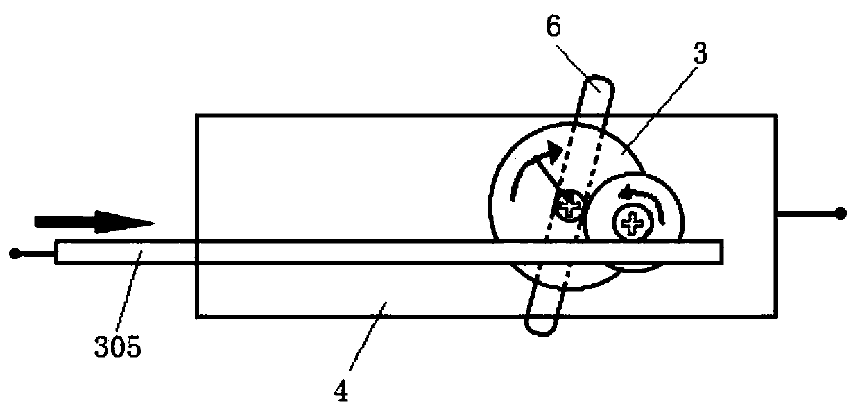
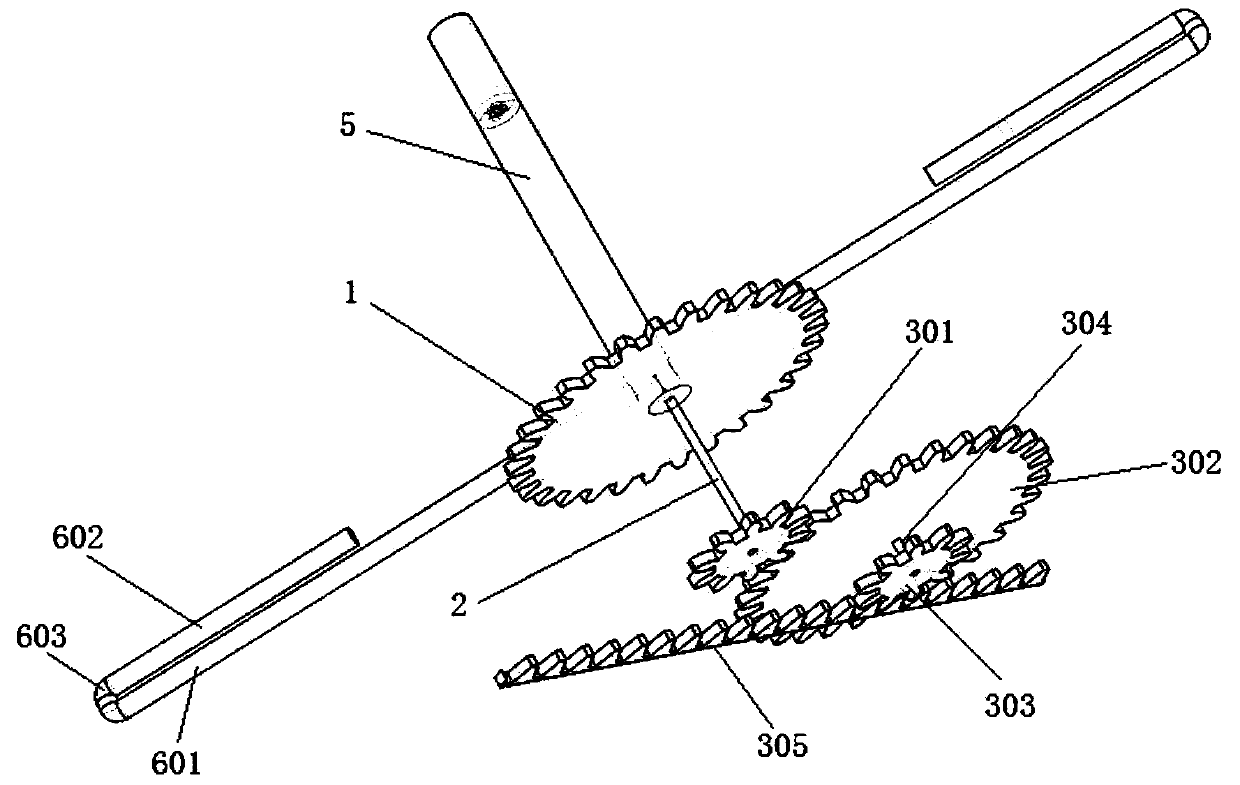
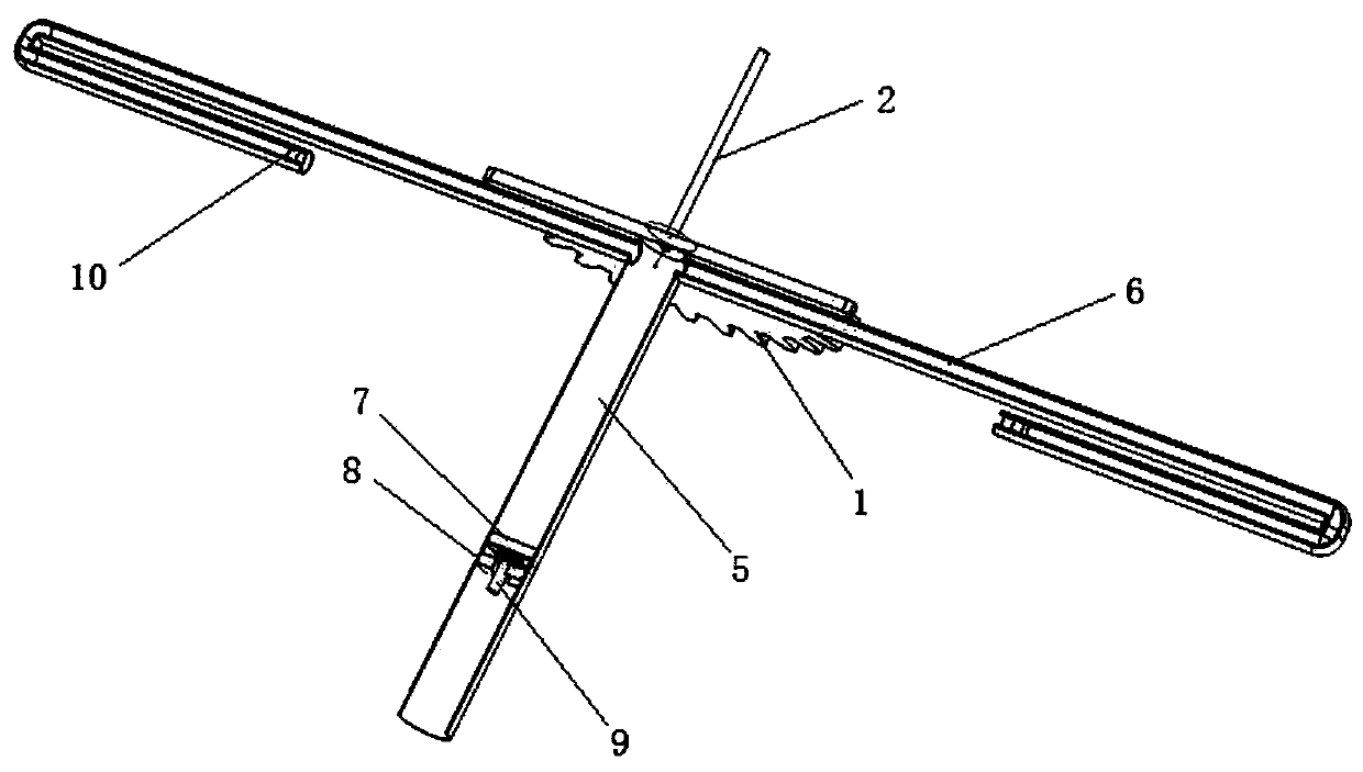
[0019] Such as figure 1 , The rack 305 is placed in the guide rail of the box body 4 and can move in translation. The rack 305 and the box body 4 are two relatively free ends of the inertial capacity. Such as Figure 2~4 , the rack 305 meshes with the second pinion 303, the bull gear 302 is connected with the second pinion 303 through the second shaft 304, the first pinion 301 meshes with the bull gear 302, and the first pinion 301 passes through the first shaft 2 It is connected with the flywheel 1, and the first rotating shaft 2 is connected with the box body 4 through bearings. Different T-shaped liquid storage pipes are installed on the flywheel 1, the axial direction is called the main pipe 5, and the radial direction is called the side pipe 6. The liquid storage pipe is sealed and filled with liquid, and flows only when the push-pull rod 9 is displaced. The side pipe 6 is a U-shaped pipe with two opposite openings. The U-shaped pipe includes a long pipe 601 , a short p...


PUM


Abstract

The invention discloses an inertial capacity device with adjustable inertial capacity. The inertial capacity device comprises a flywheel, wherein the flywheel is connected with a driving device through a first rotating shaft; the driving device is fixedly arranged on the inner side of a box body; a main pipe and side pipes which are perpendicular to each other and are communicated are arranged onone side, different from the first rotating shaft, of the flywheel; the main pipe is coaxial with the first rotating shaft and is internally provided with a main pipe piston; the main pipe piston is connected with a push-pull rod through a ball bearing; each side pipe is internally provided with a side pipe piston; protrusions are arranged at two ends of a short tube of each side pipe; an area enclosed by the main pipe piston, the main pipe, the side pipe pistons and the side pipes is filled with liquid; the liquid moves when only pushing the main pipe piston to move. The inertial capacity disclosed by the invention can be actively and continuously changed and can adapt to project demands under different conditions; the integral device is small in size and is more convenient in actual installation.

Description

technical field [0001] The invention belongs to a vibration absorbing device, in particular to an inertial capacity adjustable inertial capacity device. Background technique [0002] As a mechanical passive component, the inertial capacity proposed earlier solved the single-end problem of mass components. When a pair of forces act on the two ends of the inertial capacity, the acceleration of the two ends is proportional to the force, and the proportional value is the "inertia capacity". The new mechanical vibration isolation network composed of "inertia-spring-damper" is widely used in the fields of vehicle suspension vibration isolation, building vibration isolation and high-performance motorcycle steering compensation. Due to the relatively simple structure and relatively good effect of this kind of passive inertia, it is widely used in a wide range of applications. Currently, there are ball screw inertia, rack and pinion inertia, and hydraulic inertia. [0003] The iner...

Claims


Application Information

Patent Timeline
Patent Type & Authority Patents(China)
IPC IPC(8): F16F15/31
CPCF16F15/31
Inventor 刘恪涵彭琛邓强储鹏鹏胡银龙
Owner HOHAI UNIV
Learn More