Supercharge Your Innovation With Domain-Expert AI Agents!

Constant-rate exhaust gas treatment system

A flow treatment system and exhaust gas technology, applied in the pipeline system, control/regulation system, flow control, etc., can solve the problems of high equipment cost, increased operation and maintenance costs, and high waste gas treatment costs, and achieve the effect of avoiding negative pressure backflow

Active Publication Date: 2019-09-10
TRIUMPH PHOTOVOLTAIC MATERIAL CO LTD
View PDF8 Cites 0 Cited by
  • Summary
  • Abstract
  • Description
  • Claims
  • Application Information

AI Technical Summary

Problems solved by technology

However, if there are peaks and troughs in industrial exhaust gas emissions, and the peaks and troughs are very different, the design and processing of the equipment should be based on the peak data, which will lead to high equipment costs and increased later operation and maintenance costs. , especially in some special industries, the peak emission of industrial waste gas may be dozens or even hundreds of times of the valley value emission, which will lead to high cost of waste gas treatment

Method used


Image

  • Constant-rate exhaust gas treatment system

Examples


Embodiment Construction

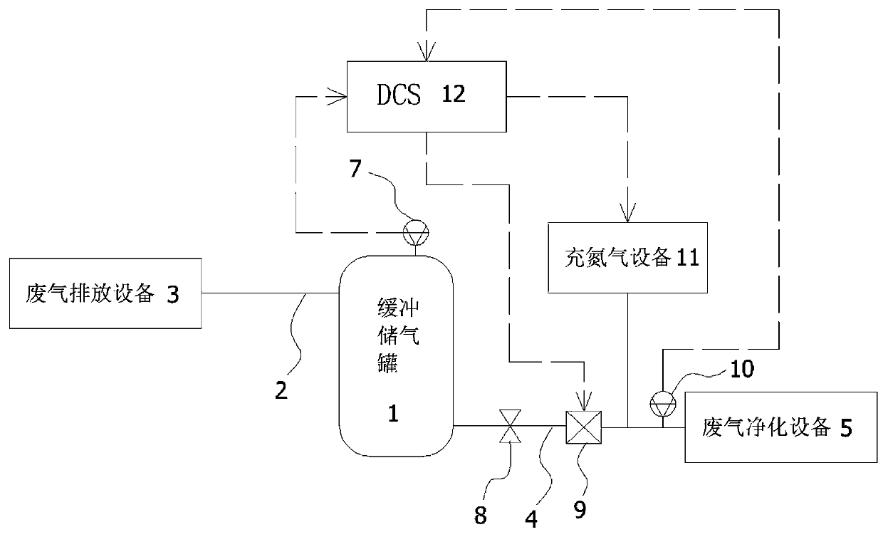
[0017] Such as figure 1 As shown, the present invention provides a constant flow treatment system for exhaust gas, including a buffer gas storage tank 1, the inlet of the buffer gas storage tank 1 is connected to the exhaust gas discharge device 3 through the intake pipe 2, and the outlet of the buffer gas storage tank 1 is connected through the outlet pipe 4 Exhaust gas purification equipment 5; a first vacuum gauge 7 is provided on the top of the buffer gas storage tank 1; a shut-off valve 8, a vacuum pump 9 and a second vacuum gauge 10 are arranged in the pipeline of the gas outlet pipe 4 along the gas outlet direction; the vacuum pump 9 and the second vacuum gauge The pipeline between gauges 10 is also connected with nitrogen charging equipment 11.

[0018] The constant current processing system also includes a DCS12, the first vacuum gauge 7 and the second vacuum gauge 10 are connected to the input interface of the DCS12, and the output interface of the DCS12 is connected...


PUM


Abstract

The invention discloses a constant-rate exhaust gas treatment system. The constant-rate exhaust gas treatment system comprises a buffering gas storage tank, wherein an inlet of the buffering gas storage tank is connected with an exhaust gas emission device through a gas inlet pipe, and an outlet of the buffering gas storage tank is connected with an exhaust gas purification device through a gas outlet pipe. A tank body of the buffering gas storage tank is provided with a first vacuum gauge. A shut-off valve, a vacuum pump and a second vacuum gauge are sequentially arranged on the gas outlet pipe in the gas outlet direction. A nitrogen filling device is connected to the portion, between the vacuum pump and the second vacuum gauge, of the gas outlet pipe. The constant-rate exhaust gas treatment system further comprises a DCS, wherein the first vacuum gauge and the second vacuum gauge are connected with an input interface of the DCS, and an output interface of the DCS is connected with the vacuum pump and the nitrogen filling device. The exhaust gas emission device discharges exhaust gas into the buffering gas storage tank through the gas inlet pipe, and the DCS controls the vacuum pump to operate according to the vacuum degree in the buffering gas storage tank, so that the flow rate of the exhaust gas is kept constant; and meanwhile, the DCS controls the nitrogen filling device to operate according to the vacuum degree, fed back by the second vacuum gauge, of the front end of the exhaust gas purification device, so that the exhaust gas purification device is maintained at aninlet working pressure.

Description

technical field [0001] The invention relates to the technical field of industrial waste gas treatment equipment, in particular to a waste gas constant flow treatment system. Background technique [0002] Industrial waste gas refers to the gas containing pollutants produced by fuel combustion or process in the factory area of ​​the enterprise. Usually, industrial waste gas needs to pass through the waste gas treatment device to purify the waste gas before being discharged into the atmosphere. [0003] At present, there are four types of industrial waste gas treatment methods: [0004] 1. Electric capture method: Use high-voltage static electricity to capture harmful particles or tar in the gas. [0005] 2. Washing method: use water or other liquids to absorb or dissolve harmful components in the exhaust gas. [0006] 3. Adsorption method: It uses porous solid media or chemical preparations to accumulate or condense one or more components in the gas on the surface to achieve...

Claims


Application Information

Patent Timeline
Patent Type & Authority Applications(China)
IPC IPC(8): F17D1/02F17D3/01G05D7/06
CPCF17D1/02F17D3/01G05D7/0629
Inventor 吴以军王宝玉尹乃良许德东
Owner TRIUMPH PHOTOVOLTAIC MATERIAL CO LTD
Features
  • R&D
  • Intellectual Property
  • Life Sciences
  • Materials
  • Tech Scout
  • Unparalleled Data Quality
  • Higher Quality Content
  • 60% Fewer Hallucinations
Learn More