Uplink control information sending and receiving method and device

A technology for controlling information and sending methods, applied in the field of communication, can solve the problems of high carrier frequency, large path loss, failure of uplink beam links, and small coverage area.

Active Publication Date: 2019-09-10
HUAWEI TECH CO LTD
View PDF6 Cites 7 Cited by
  • Summary
  • Abstract
  • Description
  • Claims
  • Application Information

AI Technical Summary

Problems solved by technology

[0004] In the above method, when the UE uses the uplink beam to transmit PUCCH to the corresponding antenna Panel, the coverage area of ​​a single uplink beam in the sector is small, and the path loss of high carrier frequency is large. If the

Method used


Image

  • Uplink control information sending and receiving method and device
  • Uplink control information sending and receiving method and device
  • Uplink control information sending and receiving method and device

Examples


Embodiment Construction

[0092] The embodiment of the application provides a method for sending and receiving uplink control information. The method of the embodiment of the application can be applied to a long term evolution (long term system, LTE) system, and can also be applied to a 5G system. The 5G system is also called New wireless communication system, New Radio (NR) system or next-generation mobile communication system.

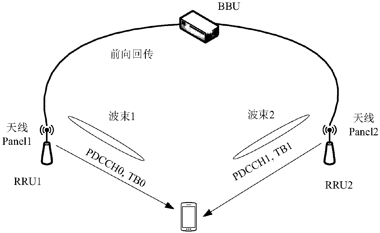
[0093] figure 1 This is a schematic diagram of a network architecture applicable to the embodiments of this application, such as figure 1 As shown, the network architecture includes terminal equipment and a base station. The base station can be a distributed base station. The distributed base station divides the traditional macro base station equipment into two functional modules according to their functions: Base Band Unit (BBU) and radio remote An end unit (Remote RadioUnit, RRU), where the BBU is used to complete functions such as baseband, main control, transmission, and cl...


PUM


Abstract

The invention provides an uplink control information sending and receiving method and device. The method comprises the following steps: a terminal device receives a first PDCCH and a second PDCCH sentby a network device, wherein the first PDCCH and the second PDCCH are transmitted in the same time unit; wherein the first PDCCH indicates a first PUCCH resource and is used for scheduling a first downlink TB, wherein the second PDCCH indicates a second PUCCH resource and is used for scheduling a second downlink TB, and the terminal device sends response information of the first downlink TB and response information of the second downlink TB to a network device on the first PUCCH resource. When one PUCCH fails to receive, the network device can acquire response information of the two downlinkTBs from the other PUCCH, so that the HARQ feedback information of the downlink TBs can be correctly received.

Description

Technical field [0001] This application relates to communication technology, and in particular to a method and device for sending and receiving uplink control information. Background technique [0002] In the fifth generation (5Generation, 5G) mobile communication system, the base station supports sending two physical downlink control channels (Physical Downlink Control Channel, PDCCH) for a user equipment (UE) in a time slot (slot). Each PDCCH is for the UE to schedule physical downlink shared channel (Physical Downlink Shared Channel, PDSCH) resources. [0003] In one implementation, the base station includes two antenna panels (Panel): antenna Panel1 and antenna Panel2. Each antenna panel is composed of multiple antenna elements. Different antenna panels can be far apart in space, and different antenna panels can Send different beams (beam). In the same slot, the antenna Panel1 sends PDCCH0 and the transmission block (Transmission Block, TB) 0 scheduled by the PDCCH0 to the UE...

Claims


Application Information

Patent Timeline
IPC IPC(8): H04L1/18H04L5/00
CPCH04L1/1829H04L5/0055H04L5/0007H04L5/0094H04L1/1854H04W72/1273H04W72/23
Inventor 陈铮张旭王建国
Owner HUAWEI TECH CO LTD
Why Eureka
Try Eureka