Signal processing method and device
A signal processing and equipment technology, applied in the field of communication, can solve problems such as interference, affecting the correct reception of reference signals, and cannot guarantee the correct demodulation of data, so as to achieve the effect of ensuring correct reception
- Summary
- Abstract
- Description
- Claims
- Application Information
AI Technical Summary
Problems solved by technology
Method used
Image
Examples
Embodiment 1
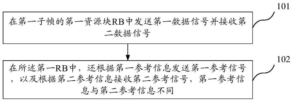
[0063] figure 1 It is a schematic flow chart of an embodiment of the signal processing method of the present invention, the method may be executed by, for example, a user equipment (User Equipment, UE for short) or a base station (evolved Node B, eNB for short), such as figure 1 As shown, can include:
[0064] 101. Send a first data signal and receive a second data signal in a first resource block RB of a first subframe;
[0065] Wherein, the first subframe is a certain subframe in the time domain, and the first RB is a certain RB corresponding to the first subframe, that is, the first RB is the first RB in the time domain. The time domain corresponding to one subframe is 12 subcarriers in the frequency domain. The resource used for communication allocated by the base station to the UE may be multiple RBs, and the transmission mode adopted by each RB (the transmission mode refers to the position, sequence, etc. transmission format) may be the same, therefore, this embodimen...
Embodiment 2
[0077] In this embodiment, the sent first reference signal and the received second reference signal occupy the same resource position in the RB, but the sequence information of the two is different.
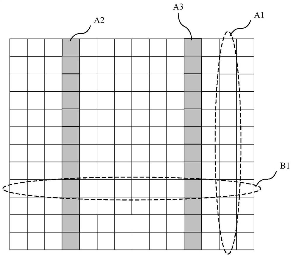
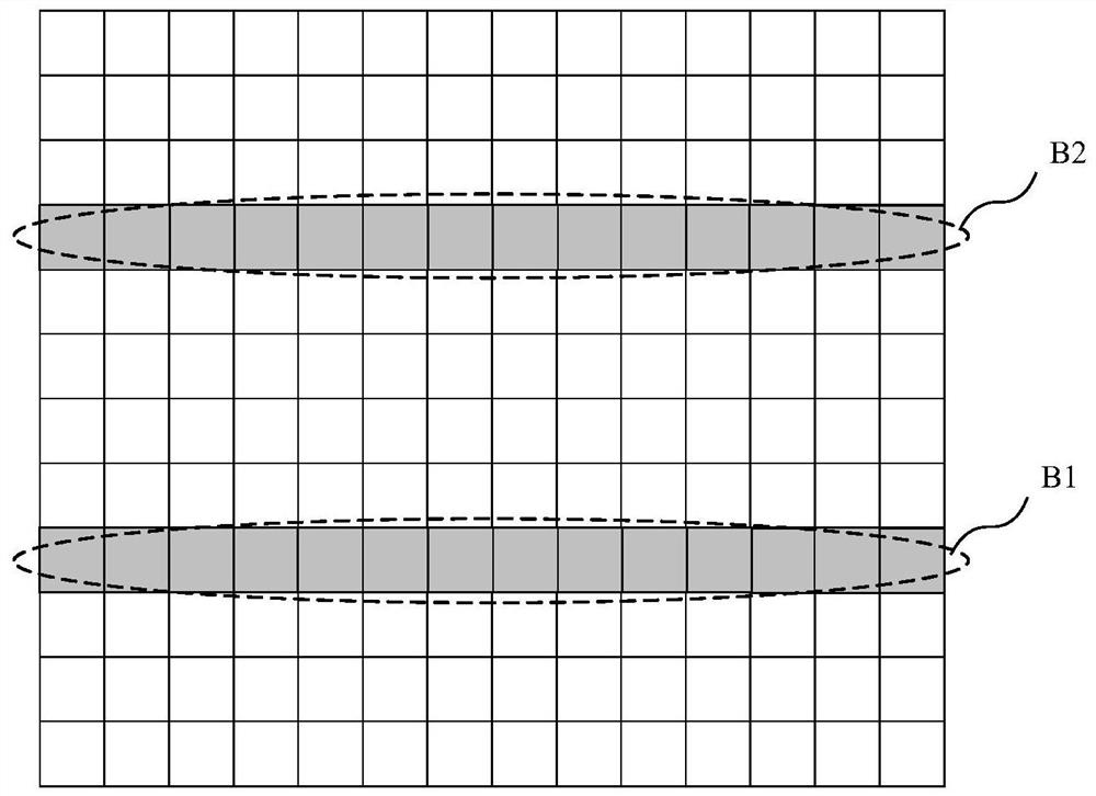
[0078] figure 2 It is a schematic diagram of the reference signal distribution in another embodiment of the signal processing method of the present invention Figure 1 ,Should figure 2 Shown is the reference signal distribution in one of the RBs.
[0079] In this example, figure 2 What is shown is a resource block (Resource Block, RB for short) in the Long Term Evolution (LTE for short) system, where the abscissa represents 14 Orthogonal Frequency Division Multiplexing (Orthogonal Frequency Division Multiplexing, referred to as: OFDM) symbols, such as figure 2 The column indicated by A1 shown in represents an OFDM symbol; the ordinate represents 12 subcarriers in the frequency domain, for example figure 2 The row indicated by B1 shown in represents one subcarrier.
[0...
Embodiment 3
[0087] In this embodiment, the sent first reference signal and the received second reference signal occupy different time-frequency resource positions in the RB.
[0088] Figure 5 It is a schematic diagram of the transmission reference signal distribution in another embodiment of the signal processing method of the present invention, Figure 6 It is a schematic diagram of distribution of received reference signals in another embodiment of the signal processing method of the present invention. Assume that sending the first reference information is on the OFDM symbols indicated by A2 and A3, and receiving the second reference signal is on the OFDM symbols indicated by A4 and A5.
[0089] Wherein, the first reference signal and the second reference signal occupy different time-frequency resources, so that mutual interference between the two can be avoided. Therefore, the sequence information of the first reference signal sent and the second reference signal received can be the ...
PUM
 Abstract
Description
Claims
Application Information
 - R&D
- Intellectual Property
- Life Sciences
- Materials
- Tech Scout
- Unparalleled Data Quality
- Higher Quality Content
- 60% Fewer Hallucinations
Browse by: Latest US Patents, China's latest patents, Technical Efficacy Thesaurus, Application Domain, Technology Topic, Popular Technical Reports.
© 2025 PatSnap. All rights reserved.Legal|Privacy policy|Modern Slavery Act Transparency Statement|Sitemap|About US| Contact US: help@patsnap.com


