
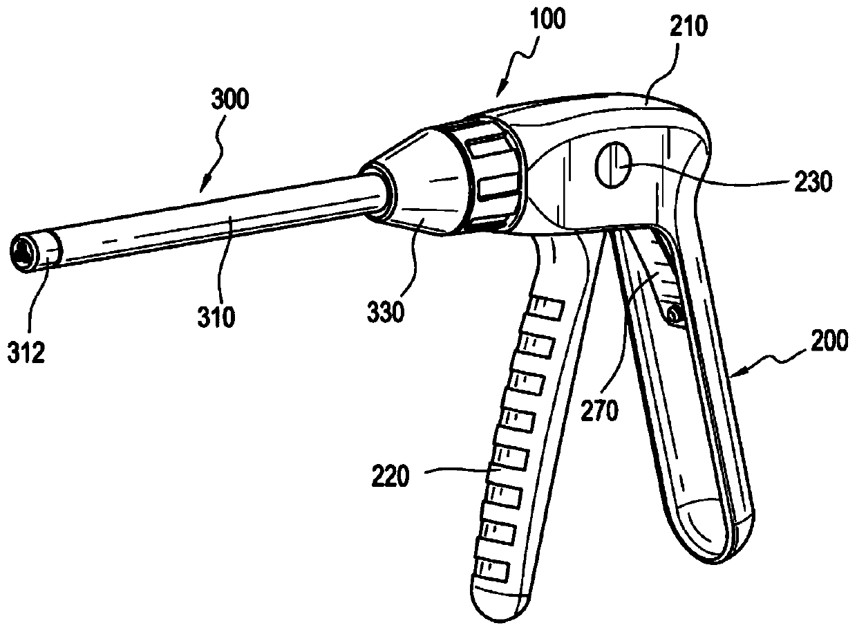
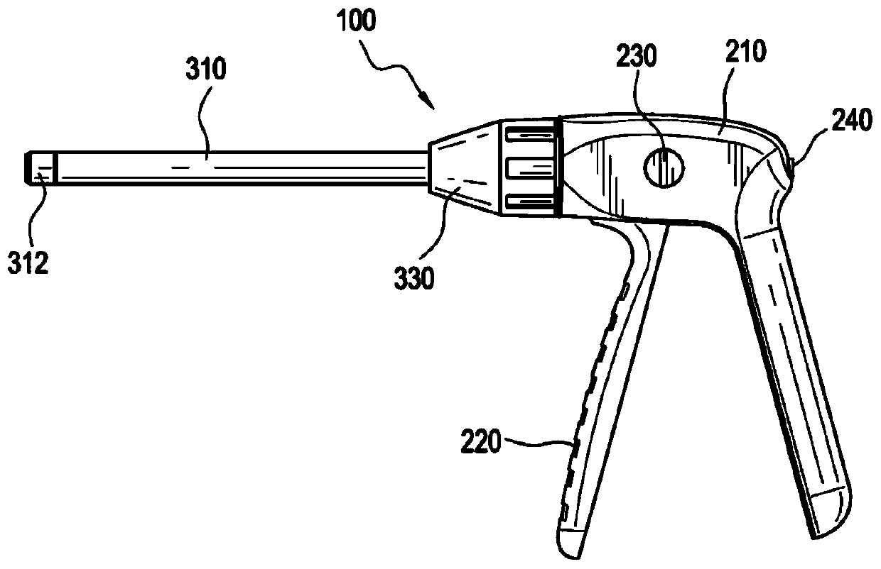
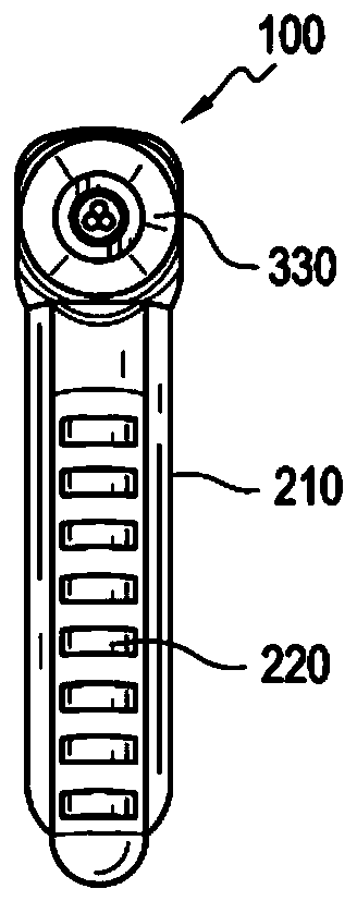
Cutting tool for surgical wires and cables

A surgical, cable-based technology, applied in the direction of manufacturing tools, shearing devices, metal processing equipment, etc., can solve the problem that it is difficult to reduce the fracture of two bone segments

Inactive Publication Date: 2019-09-10
DEPUY SUNTHES PROD LLC
View PDF0 Cites 2 Cited by
  • Summary
  • Abstract
  • Description
  • Claims
  • Application Information

AI Technical Summary

Problems solved by technology

Additionally, some of these devices can be difficult to use because it can be difficult to reduce the fracture between the two bony segments and maintain that reduction when the device is inserted

Method used


Image

  • Cutting tool for surgical wires and cables
  • Cutting tool for surgical wires and cables
  • Cutting tool for surgical wires and cables

Examples


Embodiment Construction

[0030] The description and drawings illustrate the principles of the invention. It will thus be appreciated that those skilled in the art will be able to devise various arrangements that, although not explicitly described or shown herein, embody the principles of the invention and are included within the scope of the invention. Furthermore, all examples set forth herein are, in principle, expressly intended for pedagogical purposes, to assist the reader in understanding the principles of the invention and concepts proposed by the inventor(s) to advance the state of the art, and should be considered It is understood not to be limited to these specifically stated examples and conditions. Additionally, as used herein, the term "or" means a non-exclusive (ie, and / or) unless otherwise stated (eg, "or" or "or alternatively"). Additionally, the various embodiments described herein are not necessarily mutually exclusive, as some embodiments can be combined with one or more other embo...


PUM


Abstract

A device for cutting a surgical cable including a handle side including first and second gripping members pivotally attached to one another, and an intervention side including an outer tubular member,an inner tubular member within the outer tubular member having a coupling member attached on a proximal end, and a movable pinion attached on a proximal end of the coupling member. The distal end ofthe second gripping member is attached to a proximal end of the movable pinion and the distal ends of the outer tubular member and inner tubular member have at least two openings that are off-center but substantially aligned to allow a surgical cable or wire to pass through and to exert a shearing force on the cable or wire when the inner tubular member rotates with respect to the outer tubular member in response to compressing the first and second gripping members.

Description

technical field [0001] Various exemplary embodiments disclosed herein generally relate to cutting tools for cables. Background technique [0002] A common requirement in orthopedic surgery is to anchor together two or more elements, such as bone fragments, two or more bones, or a combination of soft tissue and bone. This has been accomplished with a number of devices, such as bone bolts (which penetrate two bones and use nuts to pull the segments together), bone screws and interconnecting plates, wires encircling at least two bones, or sutures. [0003] Typically such devices require a relatively large access opening through the surrounding and / or overlying tissue to implant the anchoring device. The enlarged access site increases patient pain and prolongs recovery time. Furthermore, in some locations, it is difficult and impractical to create large access points to reach the proper site due to the surrounding joints and blood vessels. Even with a device that penetrates ...

Claims


Application Information

Patent Timeline
IPC IPC(8): A61B17/88B23D29/02
CPCB23D29/023A61B17/8863A61B17/82
Inventor T.艾伯尔S.M.博斯哈德
Owner DEPUY SUNTHES PROD LLC
Learn More