Tools for implantation and extraction of posteriorly placed lumbar articial discs including: a totally wireless electronically embedded action-ended endoscope utilizing differential directional illumination with digitally controlled mirrors and/or prisms, and a disc ball inserter , a plate extractor, and rescue disc plates

a technology for lumbar article discs and tools, applied in the field of tools for lumbar article disc implantation and extraction, can solve the problems of poor illumination, insufficient visualization, and inability to exploi

Inactive Publication Date: 2007-07-19
MOSKOWITZ FAMILY LLC
View PDF78 Cites 80 Cited by
  • Summary
  • Abstract
  • Description
  • Claims
  • Application Information

AI Technical Summary

Problems solved by technology

This is not as easily accomplished through the unilateral posterior discectomy, where visualization is limited to the side of unilateral implantation, and the middle and contralateral disc can not be visualized completely without causing undue retraction of the lumbar nerve root, and even then, full visualization is not adequately achieved.
In that design the illumination is provided by a tube lateral to the instrument inside the disc space which might endanger the nerve root by over-retraction, and would provide poorer illumination by not focusing on the center of field of vision.
Furthermore they are purely used for illumination / video, and they do not exploit our innovative technology of an induction coil thermoelectric converter to enhance wireless xenon light.
They do not use controlled directional deflectors to modulate light intensity and direction.
They do not have laser surgical tool capacities.
They are not capable of wireless transmission to palm pilots, or cell phones.

Method used


Image

  • Tools for implantation and extraction of posteriorly placed lumbar articial discs including: a totally wireless electronically embedded action-ended endoscope utilizing differential directional illumination with digitally controlled mirrors and/or prisms, and a disc ball inserter , a plate extractor, and rescue disc plates
  • Tools for implantation and extraction of posteriorly placed lumbar articial discs including: a totally wireless electronically embedded action-ended endoscope utilizing differential directional illumination with digitally controlled mirrors and/or prisms, and a disc ball inserter , a plate extractor, and rescue disc plates
  • Tools for implantation and extraction of posteriorly placed lumbar articial discs including: a totally wireless electronically embedded action-ended endoscope utilizing differential directional illumination with digitally controlled mirrors and/or prisms, and a disc ball inserter , a plate extractor, and rescue disc plates

Examples


Embodiment Construction

The Medical Device

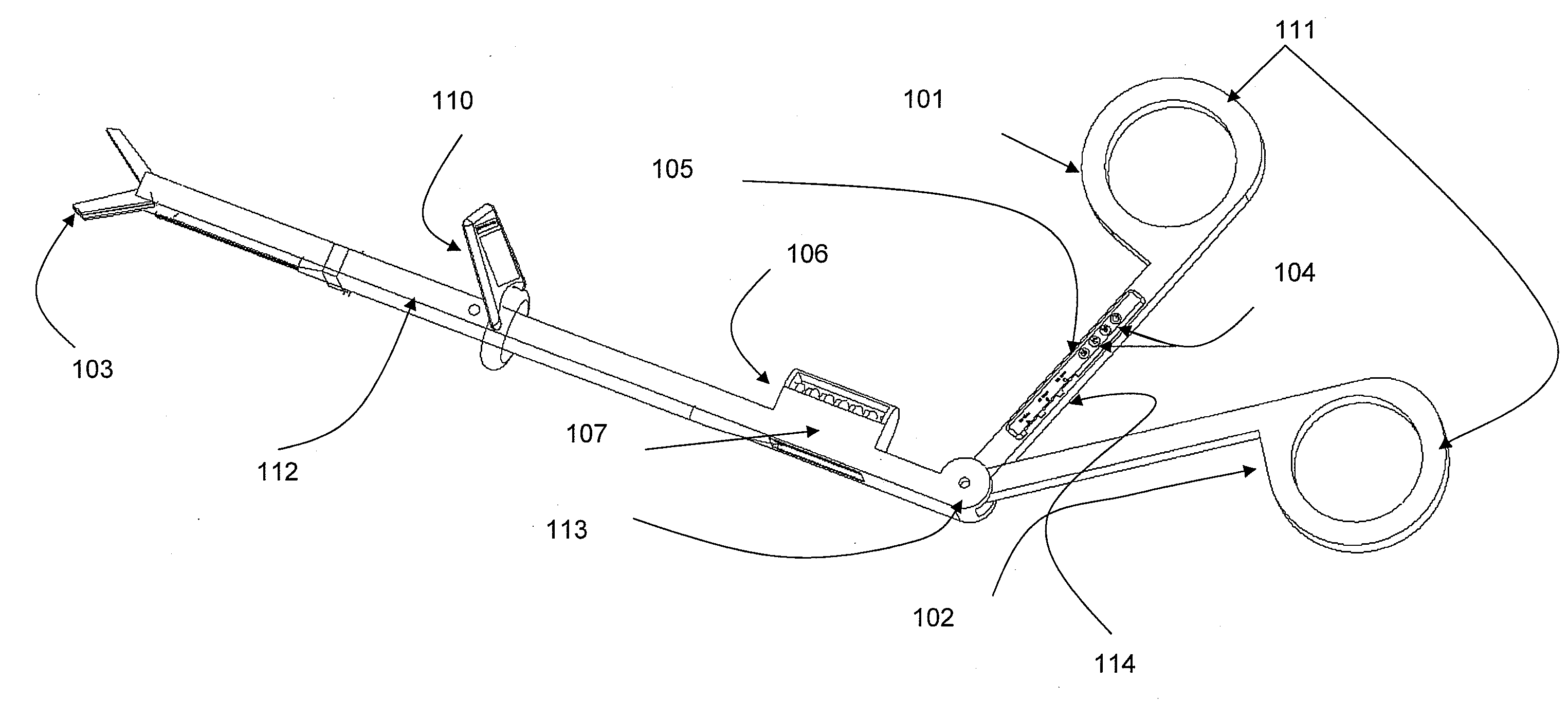
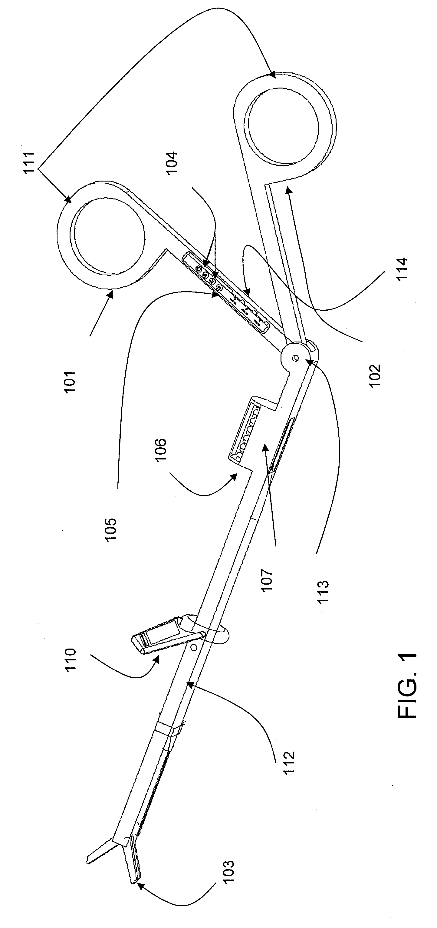
[0040]FIG. 1 illustrates a prospective view of the TWEEAE endoscope having digital inserts 111. This figure demonstrates the medial and distal manipulators 101, 102 which control the opening and closing of the pituitary forceps end manipulator 103. Also illustrated is an on board electronics panel 104 located on the lever 105 of the medial manipulator 101. The electronics panel 104 preferably includes system removable memory 114. Located on the proximal portion of the endoscopic body 112 is the laser and visible light source with cooling apparatus 106 and battery, light, laser compartment 107. Located distal to this component 107 is the mounted system viewing screen 110. The TWEEAE endoscope 100 preferably includes an adjustable manipulator angle of attack 113. We will now describe the electrical and mechanical functioning of the TWEEAE 100.

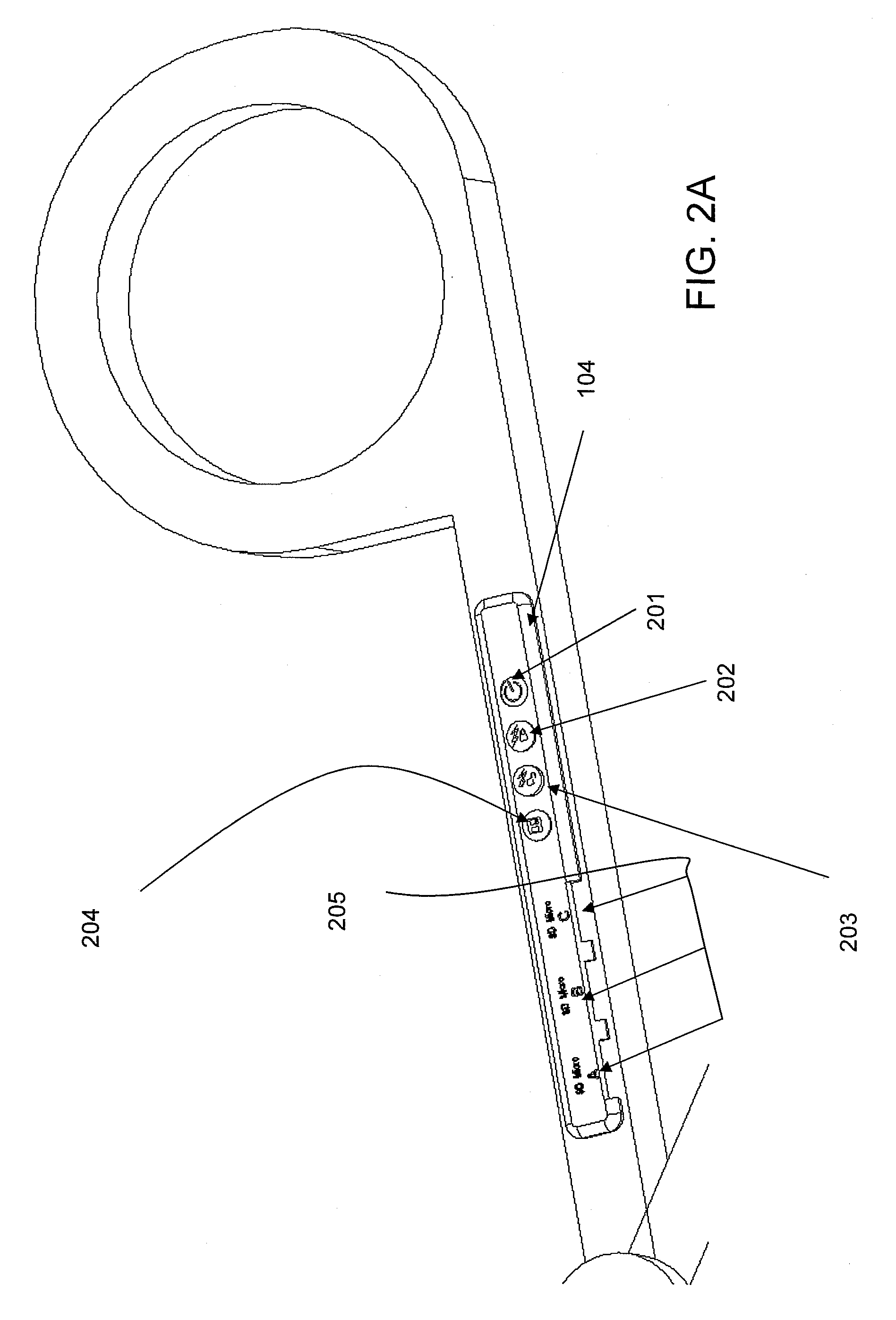
[0041]FIG. 2A illustrates an enlargement of the on board electronics panel 114. In order to power up the instrument to init...


PUM


Abstract

A hand manipulated endoscopic medical device is disclosed. The medical device includes a body having a proximal end, which is hand manipulated, and a distal end which includes a manipulator. A light emitting device is centrally disposed at the distal end. An imaging device is centrally disposed at the distal end for imaging at least a portion of the region illuminated by the light emitting device. Also disclosed is a tool for extracting an artificial lumbar disc from between a pair of vertebral plates. The extraction tool includes a handle, a member for transmitting force, and a sharpened end, specially configured to be placed between the artificial disc and the vertebral plate. Further disclosed is a tool for implanting or explanting a ball to or from an artificial lumbar disc. The implanter/explanter includes a pinion shaft and a pinion shaft enclosure. A tightening knob is disposed at the proximal end of the shaft enclosure and coupled to the pinion shaft. A pinion is disposed at the distal end of the pinion shaft. A grappling device is disposed at the pinion, and it includes a pair of semi-circular rings. When the pinion is rotated, the semi-circular rings move relative to one another and are capable of grasping or releasing the ball.

Description

[0001] This application is continuation-In-Part of copending application Ser. No. 10 / 964,633, filed on Oct. 15, 2004, which claims the benefit under Title 35, U.S.C. §119 (e) of U.S. provisional application 60 / 578,319 filed on Jun. 10, 2004; 60 / 573,346 filed on May 24, 2004; 60 / 572,468 filed on May 20, 2004; 60 / 570,837 filed on May 14, 2004; and 60 / 570,098 filed on May 12, 2004, the entire contents of which are hereby incorporated by reference and for which priority is claimed under 35 U.S.C. § 120.BACKGROUND OF THE INVENTION [0002] The history of artificial disc placements in the entire human spine, and in particular the lumbar spine has been thoroughly reviewed in our previous co-pending patent application Ser. No. 10 / 964,633, filed on Oct. 15, 2004, co-pending patent application Ser. No. 11 / 487,415, filed Jul. 17, 2006, and in our issued U.S. Pat. No. 7,083,650. In our '650 patent, we described the surgical posterior unilateral placement of an artificial lumbar disc. Prior to its...

Claims


Application Information

Patent Timeline
Patent Type & Authority Applications(United States)
IPC IPC(8): A61B1/00A61B1/06
CPCA61B1/00016A61B1/00117A61B1/00052A61B1/3135A61B17/29A61B2017/2932A61F2/442A61F2/4611A61F2002/30523A61F2002/3069A61F2002/443A61F2002/4619A61F2002/4627A61F2220/0025A61B1/07A61B1/0684A61B1/0676A61B1/05A61F2/44A61B1/00114A61B1/00048A61B1/00022A61B1/00039A61B1/00042
Inventor MOSKOWITZ, NATHANMOSKOWITZ, MOSHEH T.
Owner MOSKOWITZ FAMILY LLC
Why Eureka
Try Eureka