Devices, systems and/or methods for myopia control

A technology of myopia and micro-lens, which is applied in glasses/protective glasses, glasses/goggles, instruments, etc., and can solve problems such as the failure of emmetropization process

Active Publication Date: 2022-02-11
BRIEN HOLDEN VISION INST (AU)
View PDF9 Cites 0 Cited by
  • Summary
  • Abstract
  • Description
  • Claims
  • Application Information

AI Technical Summary

Problems solved by technology

Non-emmetropic eyes cause failure of this active emmetropic process

Method used


Image

  • Devices, systems and/or methods for myopia control
  • Devices, systems and/or methods for myopia control
  • Devices, systems and/or methods for myopia control

Examples


Embodiment 1

[0254] Example 1: Three-layer micro lens array

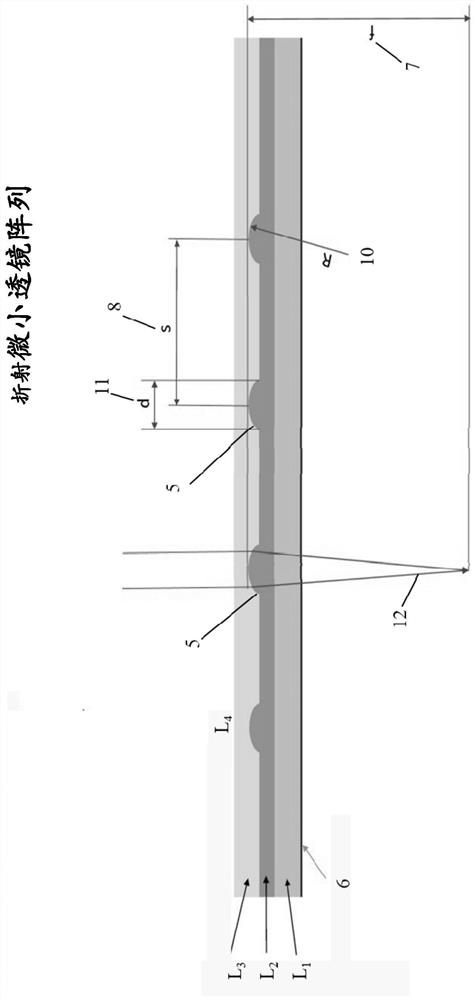
[0255] FIG. 1 shows an exemplary embodiment of a multilayer microlens array in a side view, not to scale. L 1 The layer is a transparent foil used as a substrate for the microlens array. The foil is a plastic polymer, however other suitable materials may also be used. In this example, L 2 The layer contains many microlenses, which are shown in side view in Fig. 1 as layer L 2 Small surface height 5 on the surface. In this embodiment, the diameter (d) or 11 is approximately 0.1 mm for each microlens. The focal path of light entering the microlens array is exemplified at 12 in FIG. 1 . L 2 The material used in the layers is another plastic polymer, however other suitable materials can also be used. In this example, L 2 The filling ratio in the layer is approximately 10%. L 3 layer is covered by L 2 layer of protection. L 3 The material used in the layers is plastic adhesive, however other suitable materials may als...

Embodiment 2

[0258] Example 2: Three-layer micro lens array

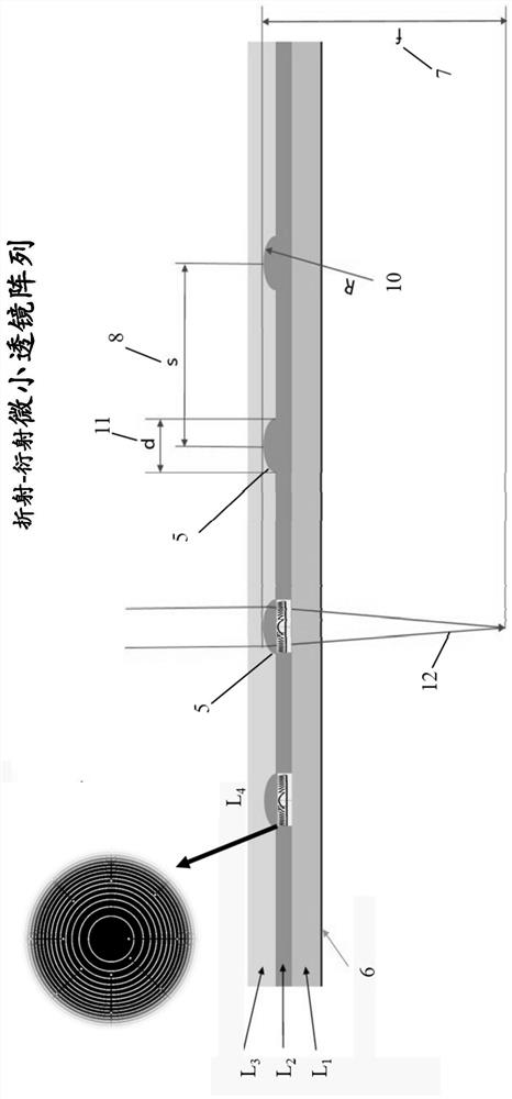
[0259] figure 2 An exemplary embodiment of a multilayer microlens array is shown in side view. In this example, the microlenses are found on the surfaces of two separate layers in the microlens array. L 13 layer is a transparent foil used as a substrate for the microlens array, and it also contains a part of the microlenses 18, which in this embodiment are in figure 2 The small surface height 18 is shown in side view. Foil is a plastic adhesive. In this example, L 14 The layer contains many microlenses 17 concentric with microlenses 18, and the microlenses 17 are in figure 2 shown in side view as layer L 14 Small bumps 17 on the surface. In this embodiment, the diameter (d) or 19 is approximately 0.1 mm for each lenslet. The focal path of light entering the microlens array is at figure 2 In 20 demonstrations. L 14 The material used in the layers is a plastic polymer, however other suitable materials may also be u...

Embodiment 3

[0261] Example 3: Two layers of tiny lens array

[0262] Figures 3A to 3E A non-limiting exemplary embodiment of a microlens array relative to a spectacle lens system is depicted in side view. There are many other suitable implementations of using tiny lenses on spectacle lenses, which are in Figures 3A to 3E not shown, but would be obvious to those skilled in the art. The geometry of the lenslets may depend on many factors including, but not limited to, the refractive index of the substrate layer, diameter, radius of curvature, effective focal length of individual lenslets, spacing between lenslets, or combinations thereof.

[0263] Figure 3A A spectacle lens system is depicted in which convex microlenses are molded directly into the spectacle lens, either on the front or back surface. Figure 3A A tiny lens 26 molded on the front of a spectacle lens 25 is depicted. The area closer to the eye is 27, while the area outside the spectacle lens is 28. exist Figure 3A...


PUM


Abstract

The present disclosure generally relates to a lens that provides a stop signal for nearsightedness over a substantial portion of the spectacle lens being used by the viewer. The present disclosure relates to devices, methods and / or systems for applying a stop signal for eye development using spectacle lenses in combination with microlens arrays. The present disclosure also relates to devices, methods and / or systems for modifying incident light through spectacle lenses that utilize color cues to slow the rate of myopia progression. The present disclosure relates to devices, methods and / or systems for applying a stop signal for eye development using spectacle lenses in combination with refractive and / or diffractive optical elements between 510 nm and 610 nm Conflicting or opposing optical signals are provided at the wavelengths.

Description

[0001] cross reference [0002] This application claims priority to and is related to U.S. Application No. 62 / 412,507, filed October 25, 2016, entitled "Devices, Systems and / or Methods for Myopia Control," which is incorporated by reference in its entirety in its entirety Incorporated into this article. technical field [0003] This disclosure relates at least in part to the introduction of conflicting chromatic cues at the retinal level of the wearer's eyes, which act as a stop signal for eyes that are nearsighted or may be progressing toward myopia. This disclosure also relates, at least in part, to the introduction of conflicting optical signals into the M and / or L cones at the retinal level of the wearer's eye, which may act as myopia or may be progressing towards myopia eye stop signal. This disclosure also relates at least in part to the use of refractive optical elements (ROE) and / or diffractive optical elements (DOE) in combination with spectacle lenses intended to b...

Claims


Application Information

Patent Timeline
Patent Type & Authority Patents(China)
IPC IPC(8): G02C7/04
CPCG02C7/022G02C7/06G02C7/086G02C7/104G02B3/0006G02B27/4205G02C2202/16G02C2202/20G02C2202/24
Inventor 拉维·钱德拉·巴卡拉朱克劳斯·艾尔曼凯瑟琳·菲特克帕德马贾·桑卡里杜尔格阿瑟·霍
Owner BRIEN HOLDEN VISION INST (AU)
Why Eureka
Try Eureka