
Robot gripper for industrial production

A technology for grasping hands and robots, applied in manipulators, program-controlled manipulators, manufacturing tools, etc., can solve problems such as poor grasping stability, inability to grasp various objects, single structure and function, etc., and achieve the goal of improving stability Effect

Inactive Publication Date: 2019-09-13
HENAN POLYTECHNIC UNIV
View PDF4 Cites 17 Cited by
  • Summary
  • Abstract
  • Description
  • Claims
  • Application Information

AI Technical Summary

Problems solved by technology

[0002] Industrial robots are widely used, among which the automobile and auto parts manufacturing industry is the most important application field. Typical applications of industrial robots include welding, painting, assembly, collection and placement (such as packaging, palletizing and SMT), product inspection and testing, etc.; the grabbing mechanism of the industrial robot in the prior art has a single structure and function, and is not suitable for grabbing multiple objects. Therefore, there is an urgent need for an industrial robot with a grabbing device that can grab multiple objects.
[0003] In view of the above problems, the patent with the existing patent notification number CN208100405U discloses a robot grabbing mechanism, which is provided with corresponding grabbing parts at the end of the grabbing mechanism, and the grabbing parts include suction cups, pneumatic fingers, hooks and Fork and other components, by setting multiple grabbing parts for different workpieces to achieve grabbing a variety of different workpieces, this grabbing method can only lift a corner of the workpiece, and the grabbing stability is poor

Method used


Image

  • Robot gripper for industrial production
  • Robot gripper for industrial production
  • Robot gripper for industrial production

Examples


Embodiment Construction

[0032] In describing the present invention, it should be understood that the terms "center", "longitudinal", "transverse", "upper", "lower", "front", "rear", "left", "right", " The orientations or positional relationships indicated by "vertical", "horizontal", "top", "bottom", "inner" and "outer" are based on the orientations or positional relationships shown in the drawings, and are only for the convenience of describing the present invention and Simplified descriptions, rather than indicating or implying that the device or element referred to must have a particular orientation, be constructed and operate in a particular orientation, and thus should not be construed as limiting the invention. In addition, the terms "first", "second", etc. are used for descriptive purposes only, and should not be understood as indicating or implying relative importance or implicitly specifying the quantity of the indicated technical features. Thus, a feature defined as "first", "second", etc. ...


PUM


Abstract

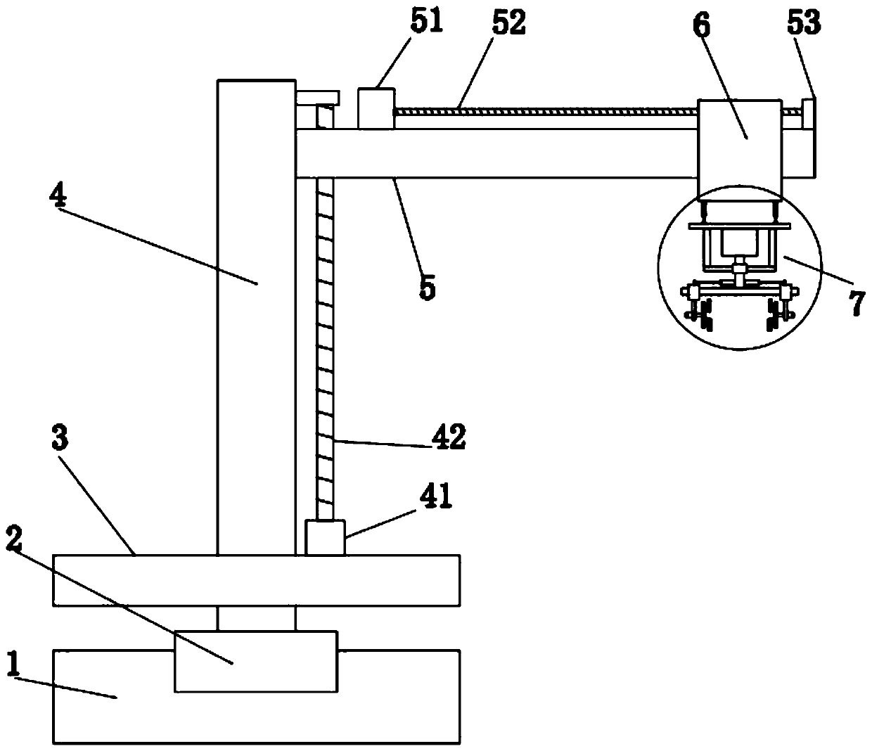
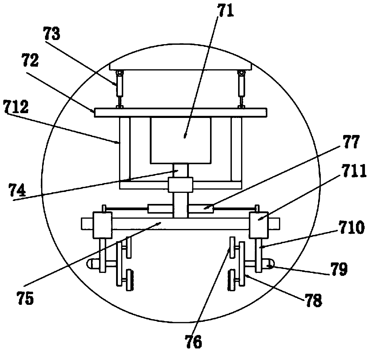
The invention discloses a robot gripper for industrial production. The output end of a rotating mechanism at the upper end of a base is connected to a rotating platform, a fixed column is vertically arranged at the upper end of the rotating platform, a cross beam is slidably arranged at the right end of the fixed column, the cross beam is connected to a lifting assembly for driving the cross beamto move up and down on the end part of the fixed column, a horizontal slide is slidably arranged on the cross beam, the horizontal slide is connected to a horizontal driving assembly for driving the horizontal slide to move left and right along the cross beam, and a gripping part for fixing to-be-gripped workpieces is arranged at the lower end of the horizontal slide. The robot gripper is improvedto overcome defects that an existing device is relatively poor in gripping stability, hard to grip surface asymmetrical objects and the like. By optimizing the gripping part, fixed parts in the gripping part are symmetrically arranged, so that the stability of workpiece gripping can be improved. The integrating degree of the robot gripper to the workpieces is further improved, and the robot gripper has remarkable progressiveness.

Description

technical field [0001] The invention relates to the technical field of industrial robot equipment, in particular to a robot grabbing hand for industrial production. Background technique [0002] Industrial robots are widely used, among which the automobile and auto parts manufacturing industry is the most important application field. Typical applications of industrial robots include welding, painting, assembly, collection and placement (such as packaging, palletizing and SMT), product inspection and testing, etc.; the grasping mechanism of the industrial robot in the prior art has a single structure and function, and cannot be suitable for grasping various objects, so there is an urgent need for an industrial robot with a grasping device that can grasp various objects. [0003] In view of the above problems, the patent with the existing patent notification number CN208100405U discloses a robot grabbing mechanism, which is provided with corresponding grabbing parts at the end...

Claims


Application Information

Patent Timeline
Patent Type & Authority Applications(China)
IPC IPC(8): B25J9/12B25J15/00B25J15/02B25J15/08
CPCB25J9/12B25J15/0028B25J15/0253B25J15/08
Inventor 马金山郑广华马小林田地岳金梦林东梅李金键
Owner HENAN POLYTECHNIC UNIV
Learn More