Traction electromagnet for gauge-changeable wheel set and locking mechanism for gauge-changeable wheel set

A traction electromagnet and gauge wheel technology, which is applied to wheels, railway car body parts, tracks of different widths, etc., can solve the problems of low efficiency, passive locking mechanism, and high investment cost, and achieve simple ground rail changing facilities. , the effect of saving cost, improving reliability and efficiency of rail change

Active Publication Date: 2019-09-13
CRRC QINGDAO SIFANG CO LTD
View PDF13 Cites 13 Cited by
  • Summary
  • Abstract
  • Description
  • Claims
  • Application Information

AI Technical Summary

Problems solved by technology

[0006] The purpose of the present invention is to provide a traction electromagnet for changing gauge wheels and a locking mechanism for changing gauge wheels, so as to solve the problem that the locking mechanisms in the existing track changing structure are all passive forms, and the track changing action needs It can only be completed with the help of external auxiliary facilities, with low efficiency and high input costs

Method used


Image

  • Traction electromagnet for gauge-changeable wheel set and locking mechanism for gauge-changeable wheel set
  • Traction electromagnet for gauge-changeable wheel set and locking mechanism for gauge-changeable wheel set
  • Traction electromagnet for gauge-changeable wheel set and locking mechanism for gauge-changeable wheel set

Examples


Embodiment Construction

[0032] The specific implementation manners of the present invention will be further described in detail below in conjunction with the accompanying drawings and embodiments. The following examples are used to illustrate the present invention, but are not intended to limit the scope of the present invention.

[0033] In the description of the present invention, it should be noted that the terms "center", "longitudinal", "transverse", "upper", "lower", "front", "rear", "left", "right", " The orientations or positional relationships indicated by "vertical", "horizontal", "top", "bottom", "inner", "outer", etc. are based on the orientation or positional relationships shown in the drawings, and are only for the convenience of describing the present invention and simplifying Describes, but does not indicate or imply that the device or element referred to must have a specific orientation, be constructed in a specific orientation, and operate in a specific orientation, and therefore sh...


PUM


Abstract

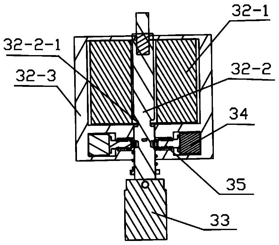
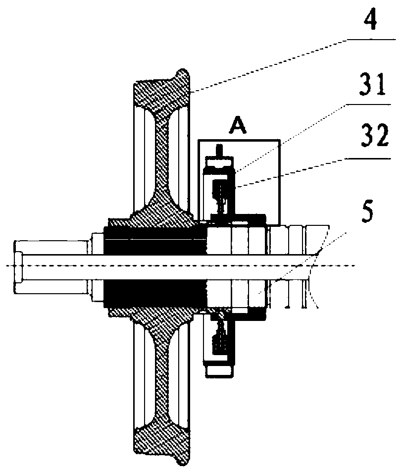
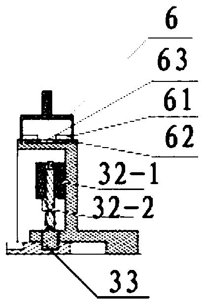
The invention relates to the field of rail vehicle gauge changing, and discloses a traction electromagnet for a gauge-changeable wheel set and a locking mechanism for the gauge-changeable wheel set. The traction electromagnet comprises a shell, a traction coil and a movable iron core; the traction coil is arranged in the shell; one end of the movable iron core penetrates through the traction coil;the movable iron core is controlled to move by the on-off of the traction coil; the other end of the movable iron core stretches out of the shell and is fixedly connected with a locking pin; the movable iron core can drive the locking pin to stretch into or leave a locking hole in a wheel hub, and the traction electromagnet further comprises at least one sucker coil and a lockpin matched with each sucker coil. The traction electromagnet can actively stretch out and withdraw, and wheel locking and unlocking can be directly achieved without the help of external equipment; and the reliability and the gauge changing efficiency of the gauge changing action are improved.

Description

technical field [0001] The invention relates to the technical field of gauge change of rail vehicles, in particular to a traction electromagnet for a gauge change wheel set and a locking mechanism for a gauge change wheel set. Background technique [0002] In order to meet the transportation requirements between tracks of different gauges in neighboring countries, bogies with different inner distances of wheel sets are often replaced at the junction. This solution is costly and time-consuming. Spain and Japan successively invented variable-gauge bogies, which can run continuously between tracks of different gauges. [0003] However, in the existing track changing structure, especially the locking mechanism is passive, and the track changing action can only be completed with the help of external auxiliary facilities, which has low efficiency and high investment cost. Contents of the invention [0004] (1) Technical problems to be solved [0005] The present invention aims...

Claims


Application Information

Patent Timeline
Patent Type & Authority Applications(China)
IPC IPC(8): B61F7/00B60B35/10B61F15/26
CPCB60B35/1045B60B35/1081B61F7/00B61F15/26
Inventor 王旭徐忠宣孔海朋王伟王利
Owner CRRC QINGDAO SIFANG CO LTD
Why Eureka
Try Eureka