Optical coating multi-angle umbrella frame and coating machine comprising same

An optical coating, multi-angle technology, used in optics, optical components, sputtering, etc., can solve the problems of inability to cover evaporation materials, increase coating costs, film defects or film deviation defects, and improve the coating yield. , The coating quality is stable, and the effect of reducing the film deficiency or film deviation defect

Pending Publication Date: 2019-09-13
江苏光腾光学有限公司
View PDF0 Cites 1 Cited by
  • Summary
  • Abstract
  • Description
  • Claims
  • Application Information

AI Technical Summary

Problems solved by technology

[0003] Each umbrella piece of the current coating umbrella stand is a curved structure, and the coating tray is arranged from top to bottom on each umbrella piece, such as image 3 , the inclination angles of the surface to be coated of the optical device to be coated on each coating tray are different from the evaporation source below and are not perpendicular to the evaporation source, so that it is easy to cause the optical device to be coated to have a A part of the surface cannot cover the evaporation material, resulting in film deficiency or film partial defects, such as Figure 4 and 5 As shown, the surface coverage of the vapor-deposited optical device to be coated can only reach 93% (convex lens) to 95% (concave lens), and the yield rate of the product is low, especially for optical devices with aspheric surfaces that are too concave or too convex. The defect is particularly obvious
[0004] In addition, it is also because the structure of the umbrella frame currently used will cause the above-mentioned film undershoot or film partial defect. In order to improve the product yield, the opening angle of the coating tray (such as Image 6 As shown), the opening angle is usually around 120° at present, so that the evaporation material evaporated from the evaporation source can cover the optical device to be coated as fully as possible, but after the coating tray is designed in this way, in order to ensure the strength of the coating tray at the same time , it is necessary to increase the area of ​​the coating tray, that is, the number of optical devices to be coated on the same area of ​​the coating tray is reduced, which also indirectly increases the coating cost

Method used


Image

  • Optical coating multi-angle umbrella frame and coating machine comprising same
  • Optical coating multi-angle umbrella frame and coating machine comprising same
  • Optical coating multi-angle umbrella frame and coating machine comprising same

Examples


Embodiment approach 1

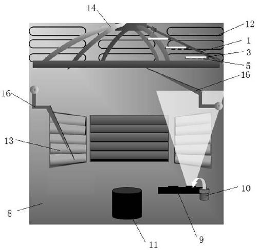
[0032] This embodiment provides an optical coating multi-angle umbrella stand, such as Figure 7 and 8 As shown, it is mainly composed of several fan-shaped umbrella pieces, and the circumference of several umbrella pieces is fixed on the umbrella ribs to form an umbrella frame 14 with an umbrella structure. Each umbrella piece is composed of a fan-shaped bracket 1 and four support plates 3 with different widths. According to the shape of the fan-shaped bracket 1, four support plates 3 are arranged on the support 1 sequentially from top to bottom, and one end of the four support plates 3 is respectively rotated and connected to the same side of the support 1, and the connection between each support plate 3 and the support 1 The included angles are respectively fixed by an angle limit mechanism 4, and the other end is a free end; Figure 9 As shown, the above-mentioned angle limiting mechanism 4 is a limiting block 401 with a supporting inclined surface, the limiting block 401...

Embodiment approach 2

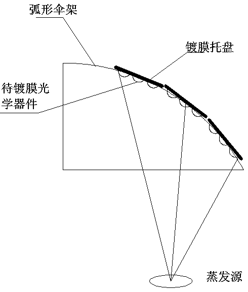
[0037] This embodiment is a further improvement of Embodiment 1. The main improvement is that in Embodiment 1, if the surface of the optical device 5 to be coated is regular and does not have an over-convex or over-concave shape, in general, each support plate 3 Adjusting to be parallel to the horizontal plane can ensure that the surface to be coated of the optical device 5 to be coated on it is directly facing the evaporation source below; For film deficiency, film deficiency or film partial defect, it is necessary to adjust the angle θ between each support plate 3 and the support 1 so that the surface to be coated of the optical device 5 to be coated faces the evaporation source to effectively avoid the above evaporation defects. In Embodiment 1, once the angle θ between the bracket 1 and the support plate 3 is fixed by the angle limiting mechanism 4, it cannot be changed. If you want to change it, you can only replace the angle limiting mechanism 4 of the required angle, tha...

Embodiment approach 3

[0042] This embodiment is a further improvement of Embodiment 1, the main improvement is that in this embodiment, as Figure 9 , the height of each support plate 3 is equal, and on each support 1, the spacing between each support plate 3 is equal to the height of each support plate 3, and the free end of each support plate 3 is fixed and folded. The limit block 401 of the angle limit mechanism 4 is provided with a folding positioning slot 7 that is fixed with the folding positioning tenon 6 and buckled in the table below. When it is necessary to adjust the angle θ between each support plate 3 and the bracket 1 to 0 ° and fixed, each support plate 3 is rotated to overlap with the bracket 1 along the rotating connection axis with the limit block 401, and the folding positioning tenon 6 at the end of the lower support plate 3 is buckled and fixed to the upper support plate 3 In the folding positioning slot 7 in the angle limiting mechanism 4, the angle θ between each support plat...


PUM

PropertyMeasurementUnit
angleaaaaaaaaaa
angleaaaaaaaaaa
cover factoraaaaaaaaaa

Abstract

The invention relates to the field of optical coating, and discloses an optical coating multi-angle umbrella frame and a coating machine comprising the umbrella frame. The umbrella frame is of an umbrella-shaped structure formed by fixing a plurality of fan-shaped umbrella pieces on umbrella ribs, and each umbrella piece comprises a fan-shaped support (1) and at least one support plate (3) used for containing a coating tray (2), each support plate (3) is parallel to each other, one end of each support plate (3) is rotationally connected to one side of a support (1), and is limited and fixed byan angle limiting mechanism (4), and the other end of each support plate (3) is a free end; and during evaporation, the to-be-coated surface of an optical device (5) to be coated on the coating tray(2) is perpendicular to an evaporation source. According to the umbrella frame, the to-be-coated surfaces of the optical devices to be coated fixed on the umbrella frame and the evaporation source below the umbrella frame are in vertical relation, so that the defects of under-film or film deviation during evaporation can be effectively avoided, and the product yield is improved.

Description

technical field [0001] The invention relates to the field of optical coating, in particular to an optical coating multi-angle umbrella stand and a coating machine comprising the umbrella stand. Background technique [0002] At present, the commonly used coated umbrella stands are mostly one-piece half-cover type, such as figure 1 (a), multi-piece half cover type such as figure 1 (b) or multi-piece flat type such as figure 1 (c), when coating, first place the optical device to be coated on the coating tray, and then fix the coating tray to the umbrella stand, such as figure 2 , put the umbrella stand above the evaporation source in the coating machine, when the environment inside the coating machine reaches the coating environment, rotate the umbrella stand while evaporating the evaporation material, and the evaporation material evaporates from the evaporation source to the surface of the optical device on the coating tray, Complete vapor deposition. [0003] Each umbrel...

Claims


Application Information

Patent Timeline
Patent Type & Authority Applications(China)
IPC IPC(8): C23C14/50C23C14/30C23C14/32G02B1/10
CPCC23C14/30C23C14/32C23C14/50G02B1/10
Inventor 黄永达
Owner 江苏光腾光学有限公司
Why Eureka
Try Eureka