a chair armrest
A technology for armrests and chairs, which is applied in the field of chair armrests and can solve problems such as poor comfort
- Summary
- Abstract
- Description
- Claims
- Application Information
AI Technical Summary
Problems solved by technology
Method used
Image
Examples
Embodiment 1
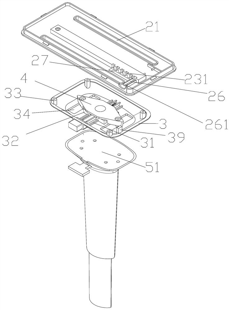
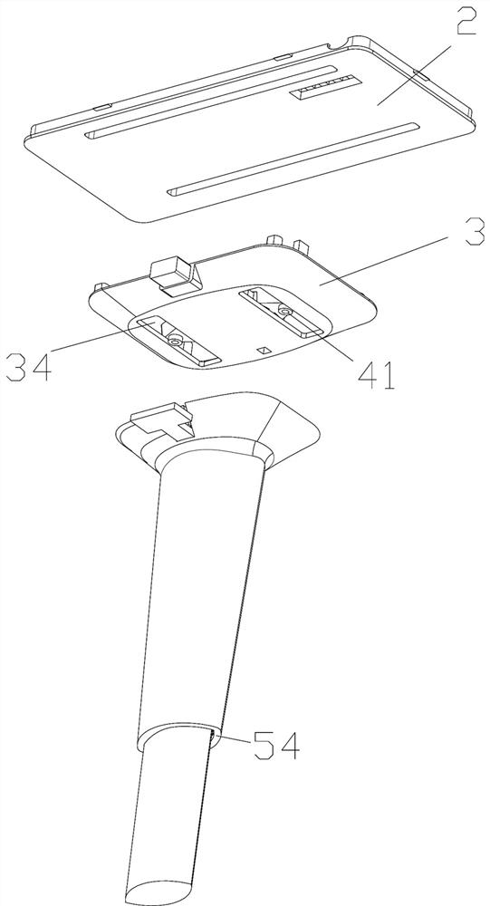
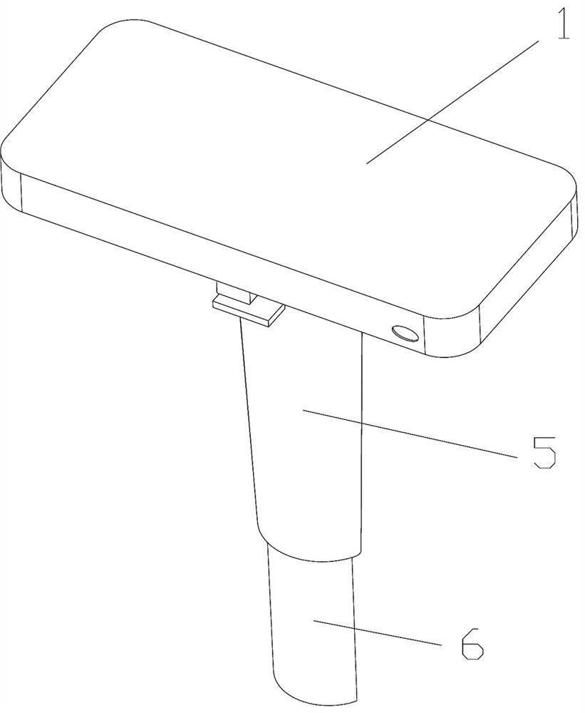
[0049] A chair armrest, comprising an armrest at the top and a support rod connected to the bottom of the armrest structure, the armrest includes a top support plate 1 at the top, a bottom connecting plate 2 detachably buckled with the top support plate and a set A horizontal adjustment assembly between the bottom connecting plate and the support rod, the horizontal adjustment assembly includes a rotary side shifting structure that can make the top support plate rotate and / or move sideways, and is arranged between the rotating side shifting structure and the bottom connecting plate The front and rear translation structure that can make the top support plate translate back and forth;
[0050] The rotating side shifting structure includes an armrest seat 3 that can rotate and move sideways relative to the support rod and has an open top installation groove on the upper part, is located in the installation groove and partially passes through the The fixed plate 4 connected to the...
Embodiment 2
[0062] The difference from the above embodiment is that the support rod includes an outer sleeve 5 whose upper end abuts against the bottom of the armrest seat and is detachably connected with the fixing plate, and the armrest connection sleeve is sleeved outside the outer sleeve. The inner sleeve 6 inside the outer sleeve and the lower end protrudes from the outer sleeve. The outer sleeve and the inner sleeve include a multi-level clamping part between them, and the multi-level clamping part includes a suitably detachable The top pressure plate 51 that is buckled on the top of the outer casing, the hanger on the upper nozzle of the outer casing and the clamping suspender 52 that is located below the top pressure plate, is set on the wall of the inner casing and can A plurality of step grooves 61 arranged sequentially from top to bottom that are fastened with the hooking portion 521 on the clamping suspender. A height control plate 522, the height control plate is provided wit...
Embodiment 3
[0065] The difference from the above-mentioned embodiment is that the inner and outer sleeves are sleeves with shuttle-shaped cross-sections, and the diameter of the outer sleeve gradually decreases from top to bottom, and the bottom end of the outer sleeve is provided for limiting the position. The edge 54 of the bottom retaining ring along the bottom edge of the buffer flap, at least one side of the pipe wall on both sides of the middle and upper part of the inner casing is provided with a step groove, and the two ends of the inner casing are on the edges 64 Correspondingly, a hook hole 63 is opened, and the folding position of the limit buffer folded plate corresponds to the end edge of the inner sleeve, and the inner side of the limit buffer folded plate is provided with a folded plate hook inserted into the hook hole part 72, the elastic member is integrally connected to the limit buffer fold plate and bulges outward beyond the outer surface of the limit buffer fold plate ...
PUM
 Abstract
Description
Claims
Application Information
 - R&D
- Intellectual Property
- Life Sciences
- Materials
- Tech Scout
- Unparalleled Data Quality
- Higher Quality Content
- 60% Fewer Hallucinations
Browse by: Latest US Patents, China's latest patents, Technical Efficacy Thesaurus, Application Domain, Technology Topic, Popular Technical Reports.
© 2025 PatSnap. All rights reserved.Legal|Privacy policy|Modern Slavery Act Transparency Statement|Sitemap|About US| Contact US: help@patsnap.com


