Pay-off rack for stainless steel horizontal water tank wire drawing machine

A water tank wire drawing machine and stainless steel technology, applied in the field of wire drawing machines, can solve the problems of poor control of the wire outlet direction, inconvenient use, and wire detachment, so as to ensure the stability of movement, avoid falling off, and prevent palm sweating slippery effect

Active Publication Date: 2019-09-17
LINYI WODA MACHINERY
View PDF17 Cites 6 Cited by
  • Summary
  • Abstract
  • Description
  • Claims
  • Application Information

AI Technical Summary

Problems solved by technology

[0004] The purpose of the present invention is to solve the shortcomings in the prior art, such as: when the traditional stainless steel horizontal water tank wire drawing machine uses a pay-off frame pay-off roller, it will turn accidentally when it is not in use, thereby releasing excess metal The wire needs to be rewound on the pay-off roller manually, and the direction of the wire after being guided by the guide wheel is not easy to control, so that when the worker adjusts the height of the guide wheel, the wire is easy to detach from the guide wheel. It is not convenient, so we propose a stainless steel horizontal water tank wire drawing machine with a pay-off frame to solve the above problems

Method used


Image

  • Pay-off rack for stainless steel horizontal water tank wire drawing machine
  • Pay-off rack for stainless steel horizontal water tank wire drawing machine
  • Pay-off rack for stainless steel horizontal water tank wire drawing machine

Examples


Embodiment Construction

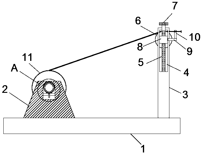
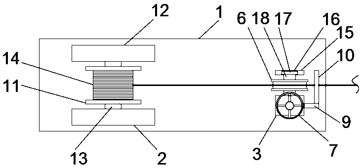
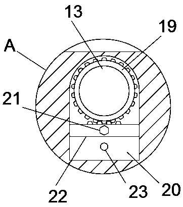
[0022] The following will clearly and completely describe the technical solutions in the embodiments of the present invention with reference to the accompanying drawings in the embodiments of the present invention. Obviously, the described embodiments are only some, not all, embodiments of the present invention.

[0023] In describing the present invention, it should be understood that the terms "upper", "lower", "front", "rear", "left", "right", "top", "bottom", "inner", " The orientation or positional relationship indicated by "outside", etc. is based on the orientation or positional relationship shown in the drawings, and is only for the convenience of describing the present invention and simplifying the description, rather than indicating or implying that the referred device or element must have a specific orientation, so as to Specific orientation configurations and operations, therefore, are not to be construed as limitations on the invention.

[0024] refer to Figure ...


PUM


Abstract

The invention discloses a pay-off rack for a stainless steel horizontal water tank wire drawing machine. The pay-off rack comprises a base, wherein a first mounting base and a second mounting base are corresponding fixedly connected to the base, a first rotating shaft is rotationally connected between the first mounting base and the second mounting base, a pay-off roller is fixedly inserted into the first rotating shaft, a groove is formed in the first mounting base, a circular gear is fixedly inserted into one end of the first rotating shaft extending to the groove, a brake stopping device is arranged in the groove, a guide wheel mounting frame is fixedly connected to one side of the base, and an open sliding groove is formed in the guide wheel mounting frame. When the pay-off roller is not used, a sliding toothed plate enables the pay-off roller to be meshed with the circular gear, then a limiting bolt is screwed into the corresponding threaded hole, so that the toothed plate is fixed, the rotation of the circular gear is further limited, namely, the rotation of the first rotating shaft is limited, accidental rotation of the pay-off roller is prevented, when the pay-off roller needs to be used, and the toothed plate is re-slid to enable the toothed plate to be separated from the circular gear.

Description

technical field [0001] The invention relates to the technical field of wire drawing machines, in particular to a pay-off frame for a stainless steel horizontal water tank wire drawing machine. Background technique [0002] Water tank type wire drawing machine has heavy horizontal water tank and flip water tank. Suitable for drawing various metal wires of medium and fine specifications, especially suitable for drawing high, medium and low carbon steel wires, galvanized iron wires, bead steel wires, hose steel wires, tungsten, molybdenum, titanium and other alloy wires, steel cords, copper wires and aluminum wires, water The box-type wire drawing machine is a small continuous production equipment composed of multiple drawing heads. After drawing step by step, and placing the drawing heads in the water tank, the steel wire is finally drawn to the required specifications. [0003] The pay-off roller of the traditional stainless steel horizontal water tank wire drawing machine w...

Claims


Application Information

Patent Timeline
Patent Type & Authority Applications(China)
IPC IPC(8): B21C47/18B21C47/28B21C47/34
CPCB21C47/18B21C47/28B21C47/3433
Inventor 路运雷路云姚国伟
Owner LINYI WODA MACHINERY
Why Eureka
Try Eureka