
Magnetorheological TOP MOUNT structure for automotive suspension with adjustable rigidity

An automotive suspension, magnetorheological technology, applied in vibration suppression adjustment, springs, shock absorbers, etc., can solve the problems of poor use effect, TPMOUNT can not realize the function of stiffness adjustment, and the spring system is not filtered, etc. Good shock effect, continuously variable damping force, smooth running effect

Inactive Publication Date: 2019-09-17
CHERY AUTOMOBILE CO LTD
View PDF11 Cites 3 Cited by
  • Summary
  • Abstract
  • Description
  • Claims
  • Application Information

AI Technical Summary

Problems solved by technology

[0004] 2. Attenuate some high-frequency vibrations with frequencies above 30HZ that are not filtered out by tires, shock absorbers & spring systems;
The TOP MOUNT with this structure cannot realize the adjustable stiffness function, and the use effect is not good

Method used


Image

  • Magnetorheological TOP MOUNT structure for automotive suspension with adjustable rigidity
  • Magnetorheological TOP MOUNT structure for automotive suspension with adjustable rigidity
  • Magnetorheological TOP MOUNT structure for automotive suspension with adjustable rigidity

Examples


Embodiment Construction

[0029] Below in conjunction with accompanying drawing, the present invention is further described:

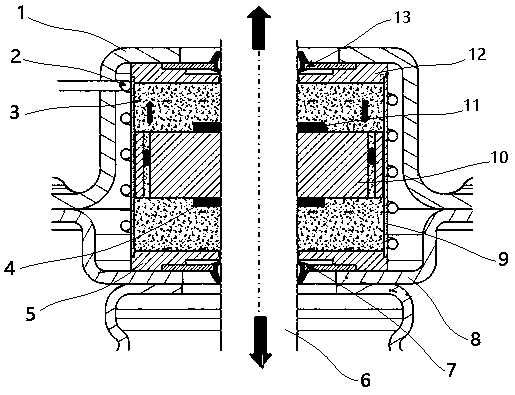
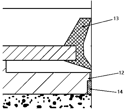
[0030] Figure 2 to Figure 4 A specific embodiment of a magnetorheological TOMPOUNT structure for automobile suspension with adjustable stiffness of the present invention is shown. figure 2 It is the structural schematic diagram of the magnetorheological TOMPOUNT structure for automobile suspension with adjustable stiffness in this embodiment; image 3 It is a partial enlarged view of the joint of the oil seal, the guide seat and the piston rod in this embodiment; Figure 4 It is a partial enlarged view of the joint of the valve body and the sleeve in this embodiment.

[0031] like figure 2 As shown, the magnetorheological TOPMOUNT structure for automobile suspension with adjustable stiffness in this embodiment includes an upper connecting plate 1 and a lower connecting plate 8, and a cavity between the upper connecting plate 1 and the lower connecting plate 8 is provided ...


PUM

PropertyMeasurementUnit
Diameteraaaaaaaaaa
The average diameteraaaaaaaaaa

Abstract

The invention relates to a magnetorheological TOP MOUNT structure for an automotive suspension with adjustable rigidity. The magnetorheological TOP MOUNT structure comprises an upper connecting plate and a lower connecting plate, and is characterized in that a sleeve is arranged in a cavity between the upper connecting plate and the lower connecting plate, an upper guide base and a lower guide base are arranged at the upper end and the lower end of the sleeve respectively, the cavity enclosed by the sleeve, the upper guide base and the lower guide base is injected with magnetorheological liquid, a piston rod penetrates through the upper connecting plate, the lower connecting plate, the upper guide base and the lower guide base, and a valve body is fixedly arranged at the position, located in the sleeve, of the piston rod; the outer cylinder surface of the sleeve is provided with an electromagnetic coil, and the electromagnetic coil controls the viscosity and fluidity of the magnetorheological liquid in the sleeve according to the up and down motion of the piston rod. The magnetorheological TOP MOUNT structure realizes the adjustability of TOP MOUNT rigidity, is ingenious, convenient to use, good in damping effect and long in service life, and guarantees the stable operation of the piston rod.

Description

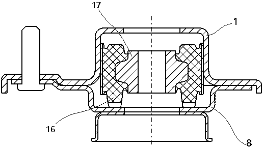
technical field [0001] The invention belongs to the technical field of automobile chassis, in particular to a magnetorheological TOMPOUNT structure for automobile suspension with adjustable rigidity. Background technique [0002] In the automobile suspension structure, the strut TOP MOUNT (that is, the installation connection structure at the upper end of the strut) is used to connect the shock absorber and the spring to the body. The role of TOP MOUNT is: [0003] 1. Bear the load; [0004] 2. Attenuate some high-frequency vibrations with frequencies above 30HZ that are not filtered out by the tire, shock absorber & spring system; [0005] 3. Control body roll. [0006] This requires the TOP MOUNT to have a small stiffness when the vehicle is moving with low amplitude and high frequency, and have a large stiffness when the vehicle is moving with high amplitude and low frequency. But the existing TOP MOUNT is a single-stage rubber block structure, such as figure 1 As sh...

Claims


Application Information

Patent Timeline
IPC IPC(8): F16F9/53F16F9/32F16F9/36
CPCF16F9/3264F16F9/3292F16F9/362F16F9/535F16F9/537F16F2222/06F16F2222/12
Inventor 平小容彭超姜海波
Owner CHERY AUTOMOBILE CO LTD
Learn More