Eureka AIR delivers breakthrough ideas for toughest innovation challenges, trusted by R&D personnel around the world.

High lossing energy composite magnetorheopectic damping device

A kind of magnetorheological damper, damper technology, applied in building components, anti-vibration and other directions, can solve the problem of magnetorheological body sealing Limited rigidity and other problems, to achieve excellent shock absorption, simple structure, and reduce the effect of earthquake response

Inactive Publication Date: 2008-09-10
SOUTHEAST UNIV
View PDF4 Cites 0 Cited by
  • Summary
  • Abstract
  • Description
  • Claims
  • Application Information

AI Technical Summary

Problems solved by technology

[0005] At present, most of the energy dissipators and dampers developed at home and abroad use a single energy dissipation mechanism or a single energy dissipation element and material to dissipate energy, and the damping force and initial stiffness provided are limited.
Therefore, the number of energy consumers (dampers) required is large, the arrangement is more troublesome, the construction procedure and cycle increase, and the building space is affected
At the same time, the magnetorheological fluid in the magnetorheological damper is prone to leakage during the vibration process. The sealing problem of the magnetorheological fluid and the high price of the magnetorheological fluid have always been important issues that have plagued the wide application of the magnetorheological damper.

Method used


Image

  • High lossing energy composite magnetorheopectic damping device

Examples


Embodiment Construction

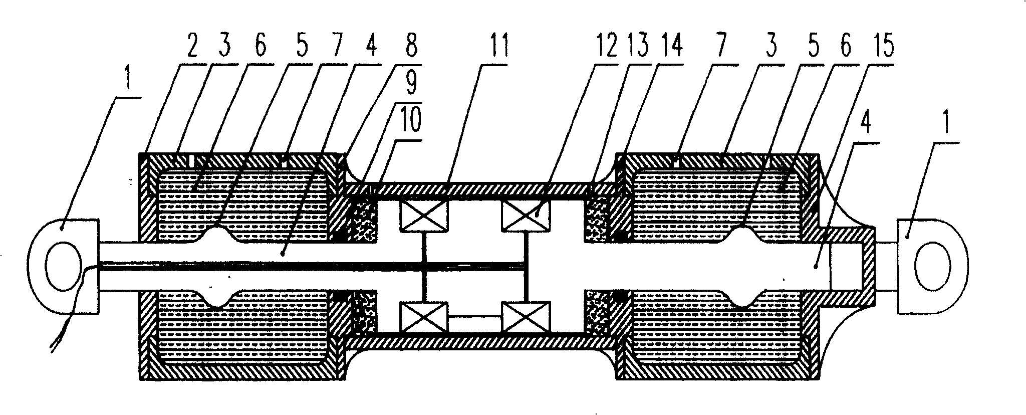
[0015] The high energy consumption composite magnetorheological damper of the invention is composed of a magnetorheological damper part and a lead damper part. The magnetorheological damper part is composed of magnetorheological damper working cylinder 11, magnetorheological damper front sealing baffle 8, magnetorheological damper rear sealing baffle 14, sealing ring 9, magnetorheological body 10, electromagnetic screw Wire pipe 12, injection hole 13 and other parts. The lead damper part is mainly composed of the lead damper working cylinder 3, the piston connecting rod 4, the piston connecting rod protrusion 5, the lead 6, the lead injection hole 7 and the sealing plates at both ends. The front sealing baffle 8 of the magnetorheological damper and the rear sealing baffle 14 of the magnetorheological damper firmly connect the working cylinder 3 of the lead damper and the working cylinder 11 of the magnetorheological damper into a whole, which not only makes the magnetorheologi...


PUM


Abstract

A high energy consumption complex magnetic change damper, it can be applied to the vibration control the structure of civil engineering, and it is high energy consumption complex damper and can apply to change damping force. There is lead damper working cylinder (3) connected with both side of the magnetic damper working cylinder (1) in this device. There is magnetic variant (10) on both side of magnetic damper working cylinder. The middle part of the piston connecting rod which is also the big diameter part locates in the working cylinder of magnetic change damper, on the circle of big diameter part is the electricity magnetic solenoid (12). There is lead (6) in the inside of the lead damper working cylinder. The left side of the piston connecting rod (4) passed through the lead damper working cylinder connects with the jointer (1). The right side of it passed through the lead damper working cylinder stretches freely to the small cylinder which is on the right side of lead damper working cylinder. The piston connecting rod which is in the working cylinder of lead damper has salience individually (5). The working cylinder of lead damper on the right side connects with the jointer (1).

Description

technical field [0001] The invention relates to an anti-seismic (vibration) damper for civil engineering structures, in particular to a composite damper capable of providing variable damping force with high energy consumption. Background technique [0002] With the development of the country and the improvement of life, the importance of high-rise building structures, towering structures, and long-span spatial structures is increasing day by day. Under the action of dynamic loads (such as wind and earthquake), these structures will undergo relatively large vibrations, which will affect the normal use and safety of the structures. However, my country is a country with many earthquakes, and most of the large and medium-sized cities in the country are located in the earthquake zone. Therefore, the problems of earthquake resistance and vibration reduction of civil structures are more prominent. The research on vibration control of such structures has important and practical sign...

Claims


Application Information

Patent Timeline
Patent Type & Authority Patents(China)
IPC IPC(8): E04B1/98
Inventor 徐赵东李爱群沙凌锋郭迎庆
Owner SOUTHEAST UNIV
Why Eureka
Eureka Blog
Learn More