
Light pier railway bridge lateral displacement measurement method

A technology of lateral displacement and measurement method, which is applied in the direction of measuring devices, complex mathematical operations, instruments, etc., and can solve problems such as indistinguishability

Pending Publication Date: 2019-09-17
YANGZHOU UNIV
View PDF0 Cites 10 Cited by
  • Summary
  • Abstract
  • Description
  • Claims
  • Application Information

AI Technical Summary

Problems solved by technology

Inability to distinguish between high-frequency dynamic displacement components caused by unbalanced forces and low-frequency pseudo-static displacement components

Method used


Image

  • Light pier railway bridge lateral displacement measurement method
  • Light pier railway bridge lateral displacement measurement method
  • Light pier railway bridge lateral displacement measurement method

Examples


Embodiment Construction

[0038] The present invention will be described in further detail below in conjunction with the accompanying drawings.

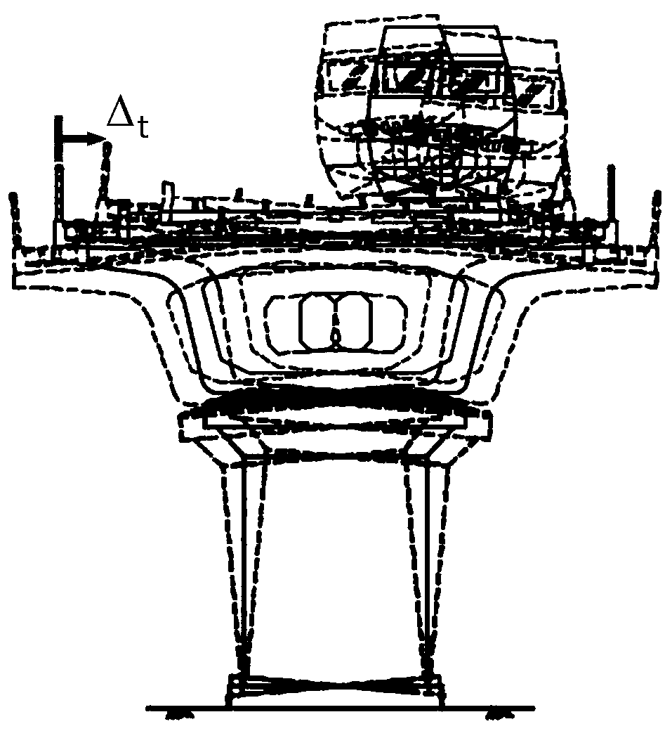
[0039] The invention relates to a method for measuring the lateral displacement of a light pier railway bridge. The method is specifically as follows: the total lateral displacement is decomposed into two parts: a high-frequency dynamic displacement component and a low-frequency pseudo-static displacement component. It uses a contact accelerometer to collect two types of data, one is the acceleration data in the vibration direction, and then uses a finite impulse response (FIR) filter to measure the dynamic displacement component; using two accelerometers to measure the vertical direction and vibration The acceleration in the direction is obtained by attenuating the dynamic component through a simple dynamic average filter to obtain the pseudo-static inclination angle, and then the deflection and rotation angle formula of the cantilever pier end is used to co...


PUM


Abstract

The present invention relates to the field of railway bridge detection, in particular to a a light pier railway bridge lateral displacement measurement method. The method comprises following steps: decomposing lateral total displacement into a high frequency dynamic displacement component and a low frequency pseudo-static displacement component, with one being accelerated velocity data in a vibration direction, and then using a finite impulse response filter to measure the dynamic displacement component; using the accelerated velocity of a vertical direction and the vibration direction measured by two accelerometers, obtains a pseudo-static tilt angle through attenuating the dynamic component by a simple momentum average filter, and then converting a low frequency dip angle data into the pseudo-static displacement component by using deflection and a rotation angle formula of a cantilever pier end; finally superimposing the dynamic displacement component and the pseudo-static displacement component, to obtain the lateral total displacement. The method mainly comprises measuring the high frequency dynamic displacement component and the low frequency pseudo-static displacement component, and can measure the light pier railway bridge lateral displacement, detect state of the railway bridge, and control safe transportation of the railway without setting a reference point.

Description

technical field [0001] The invention belongs to the field of railway bridge detection, in particular to a method for measuring the lateral displacement of light pier railway bridges. Background technique [0002] In the 1970s and 1980s, in order to save materials and adapt to the soft ground, many simply supported beam bridges with light piers were designed in the construction of the new line, with a span of 8-32m. This type of bridge structure is used in existing railway bridges in my country , especially on the freight line is widely used. [0003] Before the 1990s, due to the low speed of trains, small transportation volume, and small dynamic response of railway bridges, the contradiction between beam and pier lateral stiffness mismatch was not prominent enough. With the continuous increase of railway transportation volume, this contradiction became obvious. exposed. The transverse amplitude of most light pier bridges is relatively large, which affects the safety and ope...

Claims


Application Information

Patent Timeline
IPC IPC(8): G01B21/02G06F17/10G06F17/15G06F17/17
CPCG01B21/02G06F17/10G06F17/15G06F17/17
Inventor 陈令坤徐祥郭富城蒋丽忠张清华余志武
Owner YANGZHOU UNIV
Learn More