Water and dry beach safety monitoring equipment

A technology for safety monitoring and equipment, applied in mechanical equipment, height/level measurement, measuring devices, etc., can solve problems such as inability to balance buoyancy and stability, and achieve the effect of small data fluctuation range, small sensitivity, and improved stability

Pending Publication Date: 2019-09-17
四川省安全科学技术研究院 +2
View PDF0 Cites 2 Cited by
  • Summary
  • Abstract
  • Description
  • Claims
  • Application Information

AI Technical Summary

Problems solved by technology

[0006] The purpose of the present invention is to provide a new type of water and dry beach safety monitoring equipment for the problem that the existing water and dry beach safety monitoring equipment cannot take into account the buoyancy and stability.

Method used


Image

  • Water and dry beach safety monitoring equipment
  • Water and dry beach safety monitoring equipment
  • Water and dry beach safety monitoring equipment

Examples


Embodiment 1

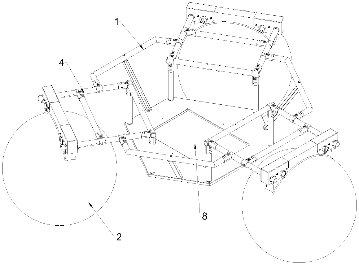
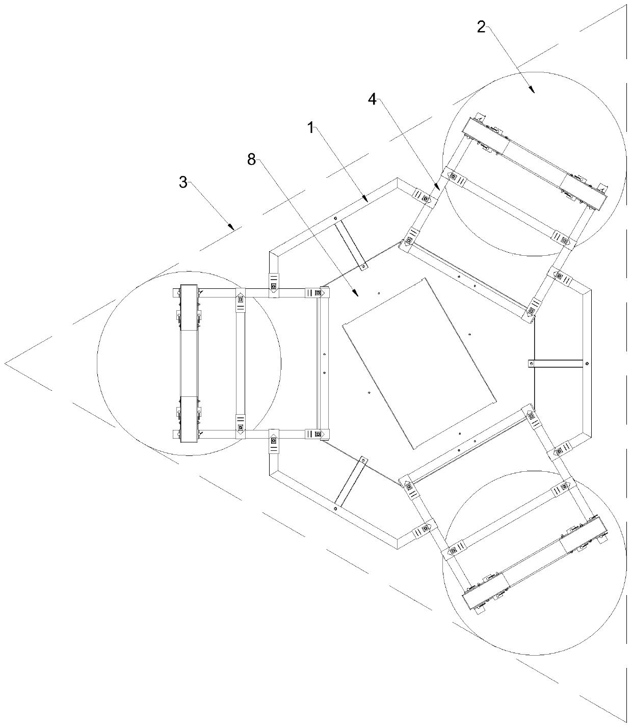
[0032] This embodiment discloses a kind of water and dry beach safety monitoring equipment, such as Figure 1-2 As shown in the figure, it includes a support for bearing and a floating ball for buoyancy support; the overall outline formed by the connection between the floating ball and the support is triangular in the direction of looking down or looking up. The overall outline is preferably an equilateral triangle.

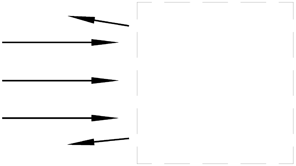
[0033] image 3 Shown is a monitoring device in the form of a traditional rectangular outline, which has a large wind load and thus poor stability. In contrast, Figure 4 Shown is the monitoring device in the form of a triangular outline in this embodiment, and this structural form can be rotated due to uneven wind load. until Figure 5 In the state shown, rotate to the state of the minimum wind load, the force is uniform, and the stability is the best.

[0034] In this embodiment, a floating ball is used to provide buoyancy for the device to ensure the sens...

Embodiment 2

[0036] Based on Example 1, in the direction of overlooking or looking up, such as Figure 1-2 , As shown in 6-8, in this embodiment, the outline of the support is designed as a hexagon, and the outline of the floating ball is circular; On the three sides, the overall outline is triangular. Preferably, the three sides of the hexagon of the bracket outline that are not connected to the floating ball form a circular array around the center of the bracket, and the three sides are parallel to the opposite side of the overall outline. Preferably, the centers of the outer circles of the three floating balls form a circular array with the center of the support, and the radii of the outer circles of the three floating balls are consistent with each other, so that the overall outer shape is an equilateral triangle. Such as figure 1 , 9 As shown, the floating ball and the bracket are connected to each other through a cross frame.

Embodiment 3

[0038] On the basis of embodiment 1 or 2, such as Figure 10-11As shown, in this embodiment, a photovoltaic panel is arranged above the support, and the photovoltaic panel is arranged obliquely, and the direction of inclination is toward the center of the support. Preferably, there are three photovoltaic panels arranged above the three floating balls respectively.


PUM


Abstract

The invention discloses water and dry beach safety monitoring equipment. The equipment comprises a bracket playing a bearing effect, and a float ball playing a buoyancy support effect, wherein the float ball and the bracket are mutually connected to form an entire external contour which presents a triangle on a lookdown or an upward direction. The monitoring equipment disclosed by the invention aims at providing novel water and dry beach safety monitoring equipment for the problem that the existing water and dry beach safety monitoring equipment cannot take both floatability and stability into consideration. The shape of the equipment can be improved to perform wind-resistant design on the basis of maintaining the weight of the monitoring equipment to be unchanged, and the equipment stability is improved in the premise of not reducing the equipment floatability. The monitoring equipment can be compatible with the data collection sensitivity and smaller data fluctuation range, thereby obtaining more accurate monitoring data.

Description

technical field [0001] The invention belongs to the technical field of safety monitoring equipment. Specifically, it relates to a safety monitoring device applied to water and dry beach areas. Background technique [0002] In recent years, landslides and debris flow accidents have occurred frequently in China, causing significant economic losses and adverse effects on the country and society. Especially in the mineral development area, the tailings pool in the mining area is formed by building a dam to intercept the valley mouth or enclosure, and is used to store metal or non-metallic mines for ore sorting and then discharge tailings or other industrial waste. A large number of abandoned sand bodies produced by ore crushing and refining are discharged in the mountain depressions and piled up layer by layer, with a volume of tens of thousands of cubic meters. The tailings reservoir has a large sedimentary volume and a large range of movement, which can reach hundreds of met...

Claims


Application Information

Patent Timeline
Patent Type & Authority Applications(China)
IPC IPC(8): G01C5/00G01S19/42G01B21/32G01F23/00
CPCG01B21/32G01C5/00G01F23/00G01S19/42
Inventor 施富强廖学燕周帅施轶凡吕恒郭利
Owner 四川省安全科学技术研究院
Why Eureka
Try Eureka