
Traffic relationship analysis method between highway toll stations

A technology for expressway and relationship analysis, applied in the field of automation, can solve the problems of low reliability, affecting the results of traffic transfer at toll stations, not considering traffic delay and discreteness, etc., to achieve the effect of eliminating errors.

Active Publication Date: 2019-09-17
CHONGQING UNIV
View PDF15 Cites 10 Cited by
  • Summary
  • Abstract
  • Description
  • Claims
  • Application Information

AI Technical Summary

Problems solved by technology

[0005] Existing technology 1: Patent CN103870890A does not consider the delay and discreteness of traffic when calculating the traffic transfer relationship between toll stations, assuming that the conditions are too ideal, this method calculates The obtained traffic transfer relationship is inaccurate, which affects the traffic transfer result of the final toll station
[0006] Prior Art 2: After the patent CN106327864A calculates the traffic transfer relationship between toll stations, it uses information entropy to measure its stability, and assigns high weight to periods with relatively small fluctuations. value, while the period with relatively large fluctuations is considered to be low in reliability and given a smaller weight. However, when calculating the flow transfer relationship between toll stations, according to the basic assumption of uniform driving, the flow transfer coefficient in the t period is calculated. When t When t is large, the assumption has little influence on the result; when t is small, the calculated result deviates greatly from the actual situation

Method used


Image

  • Traffic relationship analysis method between highway toll stations
  • Traffic relationship analysis method between highway toll stations
  • Traffic relationship analysis method between highway toll stations

Examples


Embodiment Construction

[0051] The present invention will be further described below in conjunction with the accompanying drawings and specific embodiments, so that those skilled in the art can better understand the present invention and implement it, but the examples given are not intended to limit the present invention.

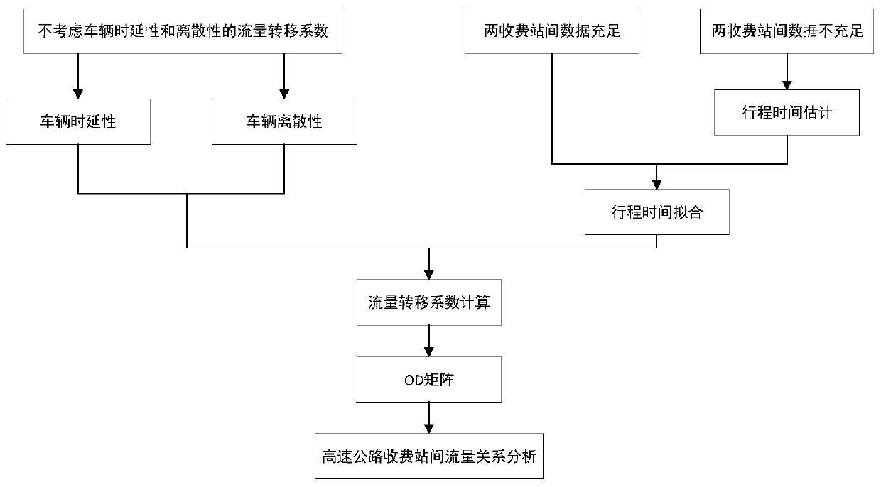
[0052] see figure 1 , a flow relationship analysis method between expressway toll stations of the present embodiment, comprising the following steps:

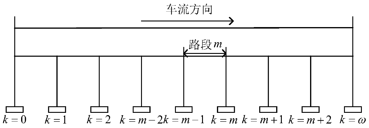
[0053]Step 1: See figure 2 , under the ideal conditions without considering the time delay and discreteness of vehicles, the flow transfer coefficient is calculated, and the flow transfer coefficient α is defined ij It is the ratio of the number of vehicles entering the road network from i toll station and leaving the road network from j toll station to the total number of vehicles entering the road network from i toll station within the time window τ, that is, in the time window τ, the flow of OD accounts for D The ratio of the...


PUM


Abstract

The invention discloses a traffic relationship analysis method between highway toll stations which comprises the following steps: step 1, assuming that vehicle intervals obey uniform distribution under an ideal condition of not considering vehicle time ductility and discreteness, and obtaining an expressway toll station flow transfer coefficient; 2, estimating the travel time of the vehicle passing through each highway toll station; step 3, fitting the distribution of vehicle travel time among all highway toll stations; 4, correcting the flow transfer coefficient between toll stations on the basis of considering the vehicle time delay; step 5, based on the step 4, further correcting the flow transfer coefficient between toll stations on the basis of considering the vehicle discreteness; and step 6, establishing a flow transfer matrix among the toll stations in combination with the steps 3 to 5. The algorithm can eliminate the error of the inter-toll-station flow relation without considering the ideal conditions of vehicle time delay and discreteness, and is more in line with the actual condition that the vehicle travels between highway toll stations.

Description

technical field [0001] The invention specifically relates to the field of automation, and in particular, relates to a flow relationship analysis method between expressway toll stations. Background technique [0002] As the economic interactions in various parts of our country become more and more frequent, more and more vehicles are driving on intercity expressways and ring expressways. Expressways have developed by leaps and bounds in my country since the 1990s. Inherent characteristics and advantages occupy an extremely important position and role in modern transportation. With the full coverage of expressway network toll data, the use of expressway network toll data to analyze expressways has become a hot spot. [0003] Since there are many toll data fields in the expressway network, and various information data of vehicles entering and leaving the road network can be obtained, while the section detection equipment can only obtain some parameters when the vehicle passes th...

Claims


Application Information

Patent Timeline
Patent Type & Authority Applications(China)
IPC IPC(8): G06F17/50G06Q50/26G08G1/01
CPCG06Q50/26G08G1/0125G06F30/20
Inventor 赵敏孙棣华和婧
Owner CHONGQING UNIV
Learn More