Spring-wrapped jack contact member

A technology of jack contacts and jacks, which is applied in the field of spring-covered jack contacts, can solve the problems of large plugging force, low contact reliability, unreliable contact, etc., and achieves improved deformability and contact reliability. High, wide range of insertion force effects

Inactive Publication Date: 2019-09-17
GUIZHOU SPACE APPLIANCE CO LTD
View PDF5 Cites 0 Cited by
  • Summary
  • Abstract
  • Description
  • Claims
  • Application Information

AI Technical Summary

Problems solved by technology

Since the crown spring contact ring 2 is fixed inside the tubular socket 1, the insertion force and separation force of this structural form are inevitably limited by the size of the pre-deformation and greatly affected by the machining accuracy. If the deformation range is small, then The pressure is small and the contact is unreliable; if the deformation is large, the pressure will be large and the insertion force will be large, not only the connector is difficult to butt, but also the deformation will cause plastic degeneration, resulting in unreliable contact
Therefore, this type of socket contact is not only difficult to manufacture, but also has low contact reliability and relatively high manufacturing costs. It cannot be widely used in occasions that require economical, high mechanical life, and large-scale vibration.

Method used


Image

  • Spring-wrapped jack contact member
  • Spring-wrapped jack contact member
  • Spring-wrapped jack contact member

Examples


Embodiment 1

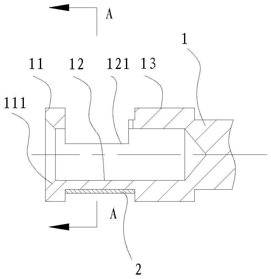
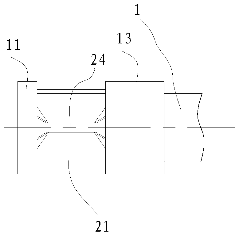
[0044] Such as Figure 1-3 , a spring socket contact, including a socket 1 and a contact ring 2. The insertion end of the socket 1 is a cylindrical body, including a guide section 11, an insertion section 12 and a support section 13. The outer diameter of the insertion section 12 is smaller than the outer diameter of the guide section 11 and the support section 13, and its side A window 121 is opened in the axial center of the wall.

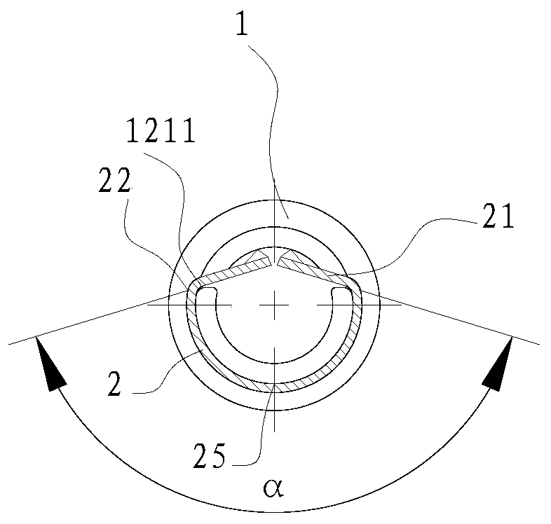
[0045] The contact ring 2 is a plate-shaped body folded into a "U" shape, including two "1"-shaped contact elastic pieces 21 and an arc segment 22 . The four vertices of the contact elastic piece 21 are bent outwards to form a guide portion 23 , and the guide portion 23 faces the outer surface of the “U” shape.

[0046] The contact ring 2 is surrounded by the mating section 12, and the two "1"-shaped contact springs 21 of the "U" shape are bent inward with a tool, so that the two "1"-shaped contact springs 21 form an obtuse angle α, and the con...

Embodiment 2

[0048] Such as Figure 4-8 The difference between the structure of embodiment 2 and embodiment 1 is that two or more windows 12 are opened on the mating section 12, and there are two or more windows 12 on the corresponding contact ring 2, and these windows and contact The rings 2 are arranged alternately and staggered in the axial direction of the socket 2, and also uniformly distributed in the radial direction, so as to balance the contact force structure of the contact pair and increase the contact area and electrical contact reliability.


PUM


Abstract

A spring-wrapped jack contact member includes a cylindrical jack and a contact ring. The sidewall of the jack is provided with a window. The contact ring wraps the window on the outer wall of the jack. The contact ring is provided with a contact spring. The contact spring is bent towards the inside of the jack and protrudes into the jack through the window. The contact ring wraps a contact section so as to achieve a wide insertion force range, a low process requirement, high contact reliability. Further, the spring-wrapped jack contact member is simple in structure, small in size, practical and convenient, and can economically meet the requirement of a situation for a long mechanical life and large-scale vibration.

Description

technical field [0001] The invention belongs to the field of electrical connectors, and in particular relates to a spring-wrap socket contact. Background technique [0002] Invention patent ZL201210273857.1 discloses an existing crown spring socket contact, its structure is as follows Figure 11 As shown, it is composed of a tubular socket 1, a crown spring contact ring 2 and a pin 3. One end of the crown spring contact ring 2 is provided with a slot and a contact strip, which is axially placed inside the tubular socket 1 and slotted The parts are fixed by pressure riveting, welding and other methods. Since the crown spring contact ring 2 is fixed inside the tubular socket 1, the insertion force and separation force of this structural form are inevitably limited by the size of the pre-deformation and greatly affected by the machining accuracy. If the deformation range is small, then If the pressure is small, the contact is unreliable; if the deformation is large, the pressu...

Claims


Application Information

Patent Timeline
IPC IPC(8): H01R13/187H01R13/02
CPCH01R13/02H01R13/187
Inventor 桂丑雷永涛李洪富余贵龙
Owner GUIZHOU SPACE APPLIANCE CO LTD
Why Eureka
Try Eureka