Pay-off device for power cables

A technology of power cables and pay-off devices, which is applied in the direction of cable laying equipment, etc., to achieve the effects of reducing costs, ensuring accuracy, and preventing bending

Active Publication Date: 2020-10-27
ZHANGQIU POWER SUPPLY CO OF STATE GRID SHANDONG ELECTRIC POWER CO +1
View PDF11 Cites 0 Cited by
  • Summary
  • Abstract
  • Description
  • Claims
  • Application Information

AI Technical Summary

Problems solved by technology

[0004] The present invention aims at the above-mentioned deficiencies in the prior art, and provides a power cable pay-off device, which solves the cumbersome installation of the current cable reel with the help of hoisting machinery, saves time and material resources, and reduces costs; Straightening is achieved through the cooperation of the first wire crimping device and the second wire crimping device, which solves the problem of cable bending, is more convenient to use, and ensures the accuracy of cutting dimensions, avoiding cost waste

Method used


Image

  • Pay-off device for power cables
  • Pay-off device for power cables
  • Pay-off device for power cables

Examples


Embodiment Construction

[0037] The following will clearly and completely describe the technical solutions in the embodiments of the present invention with reference to the accompanying drawings in the embodiments of the present invention. Obviously, the described embodiments are only some, not all, embodiments of the present invention. Based on the embodiments of the present invention, all other embodiments obtained by persons of ordinary skill in the art without making creative efforts belong to the protection scope of the present invention.

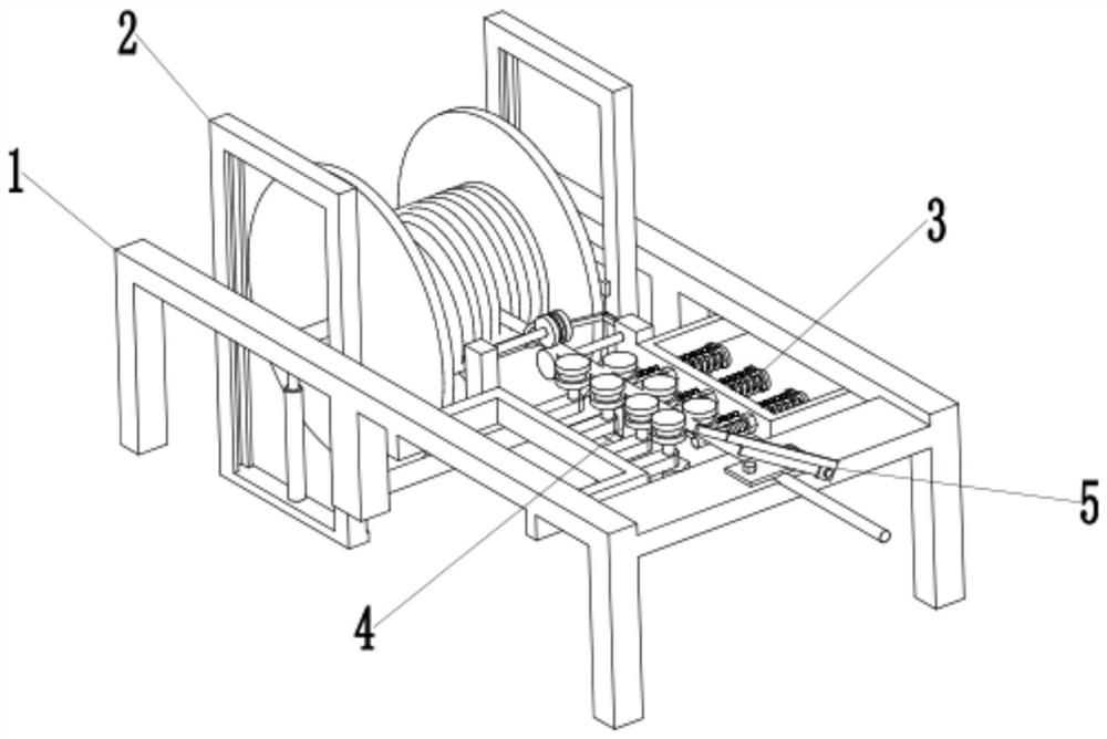
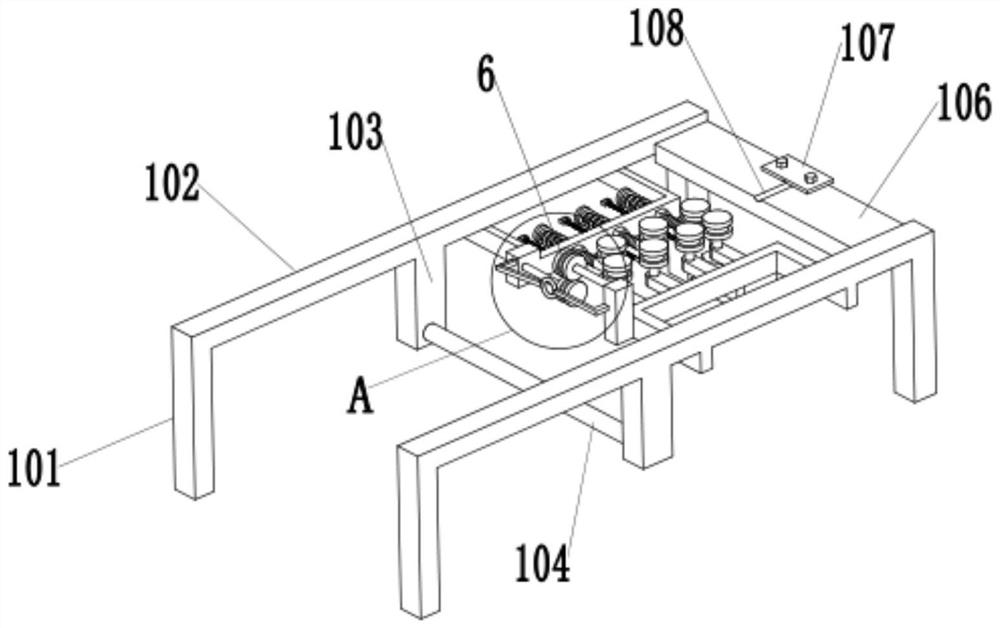
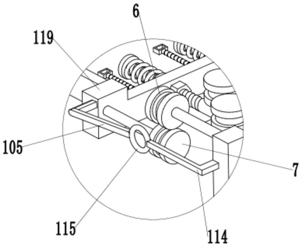
[0038] Such as Figure 1-2 As shown, a power cable pay-off device includes a frame 1, and the frame 1 includes two beams 102, one end of the two beams 102 is connected by a cutting table 106, and both ends of the beam 102 are provided with supports Leg 101, the inboard of each beam 102 is all connected with support frame 2, and described support frame 2 is provided with hydraulic cylinder 208, as Figure 6 As shown, the upper end of the hydraulic cylinder 208 i...


PUM


Abstract

The invention discloses a releasing device for a power cable. The releasing device comprises a rack. The rack comprises two cross beams. One end of one cross beam is connected with one end of the other one cross beam through a cutting table. Supporting legs are arranged at the two ends of each cross beam. The inner side of each cross beam is connected with a supporting frame. A hydraulic cylinder is arranged on each supporting frame. A lifting rod is arranged at the upper end of each hydraulic cylinder. A supporting shaft used for lifting a cable reel is arranged between the two lifting rods. The end parts of the supporting shaft are connected with the lifting rods. A wire groove is formed in the upper end face of a cutting table. A pressing plate is arranged on the wire groove. The pressing plate is connected with the cutting table through a bolt. A cutter is arranged on one side of the cutting table. One end of the cutter is rotationally connected with the cutting table. A first wire pressing device and a second wire pressing device are arranged between the cutting table and the supporting frame. The first wire pressing device and the second wire pressing device are both connected with the rack. The first wire pressing device and the second wire pressing device are oppositely arranged. A power cable penetrates through the position between the first wire pressing device and the second wire pressing device.

Description

technical field [0001] The invention relates to the technical field of power cable processing devices, in particular to a power cable pay-off device. Background technique [0002] Power cables are cables used to transmit and distribute electric energy. Power cables are often used in urban underground power grids, outgoing lines of power stations, internal power supply of industrial and mining enterprises, and underwater transmission lines across rivers and seas. In power lines, the proportion of cables is gradually increasing. Power cables are cable products used to transmit and distribute high-power electric energy in the main line of the power system, including 1-500KV and above various voltage levels and various insulated power cables. [0003] In the construction process of power cables, it is necessary to use a crane to place the entire cable reel into the pay-off device, and then manually pull the cable for release. On the device, it is time-consuming and materially ...

Claims


Application Information

Patent Timeline
IPC IPC(8): H02G1/06
CPCH02G1/06
Inventor 孟照海王允霞徐继亮张超张鸿浩周圣雄岳斌刘广军周琦李长宝
Owner ZHANGQIU POWER SUPPLY CO OF STATE GRID SHANDONG ELECTRIC POWER CO
Why Eureka
Try Eureka