
Cutter shaft structure and single shaft crusher

A technology of cutter shaft and cutter grain, which is applied in the direction of grain processing, etc., can solve the problems of high operating cost of the cutter, low protruding height of the knife grain, and increased wear of the knife grain, so as to achieve excellent processing production capacity, increase cutting output, and prolong service life Effect

Pending Publication Date: 2019-09-20
HARDEN SHREDDER TECH
View PDF0 Cites 0 Cited by
  • Summary
  • Abstract
  • Description
  • Claims
  • Application Information

AI Technical Summary

Problems solved by technology

However, the existing single-shaft crushers have the problems of low cutting and discharging efficiency, fast tool wear and high operating costs. The protruding height of the grains is low, which further leads to insufficient cutting capacity, resulting in low feeding efficiency; moreover, there is no effective measure to discharge the crushed materials in time, resulting in low discharging efficiency
If the material cannot be discharged in time, it will increase the wear of the knife grains, resulting in low output and high wear of the knife grains. For customers, it means that the cost of the knife per ton of material is high, and it is difficult to match the high output and low cost of solid waste.

Method used


Image

  • Cutter shaft structure and single shaft crusher
  • Cutter shaft structure and single shaft crusher
  • Cutter shaft structure and single shaft crusher

Examples


Embodiment Construction

[0022] In order to make the purpose, technical solutions and advantages of the embodiments of the present invention clearer, the technical solutions in the embodiments of the present invention will be clearly and completely described below in conjunction with the drawings in the embodiments of the present invention. Obviously, the described embodiments It is a part of embodiments of the present invention, but not all embodiments. The components of the embodiments of the invention generally described and illustrated in the figures herein may be arranged and designed in a variety of different configurations. Accordingly, the following detailed description of the embodiments of the invention provided in the accompanying drawings is not intended to limit the scope of the claimed invention, but merely represents selected embodiments of the invention.

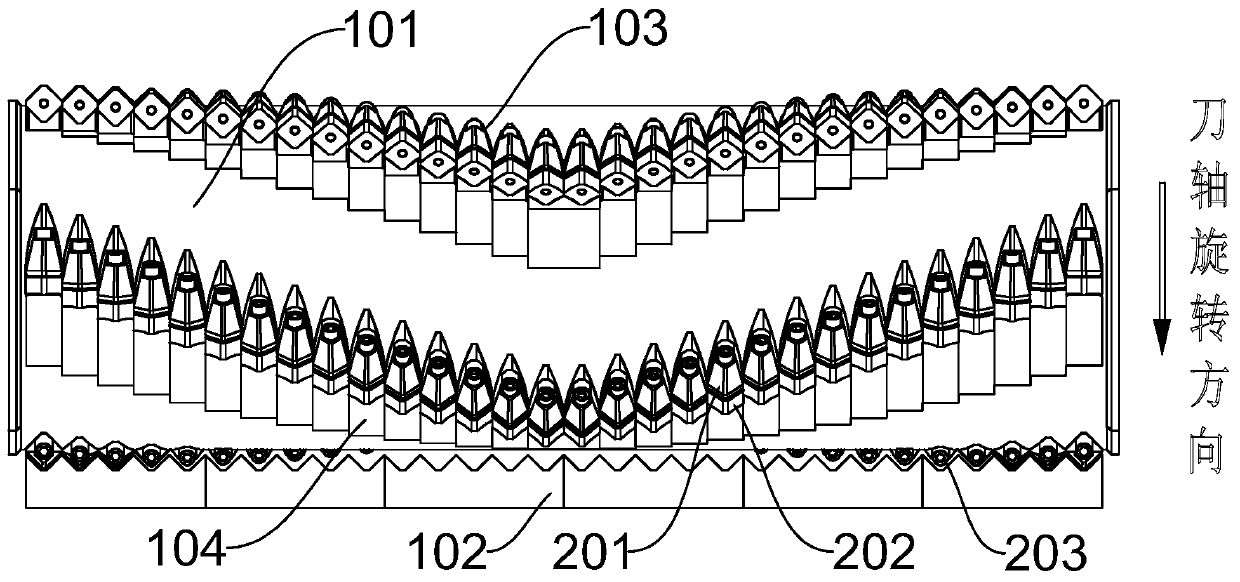
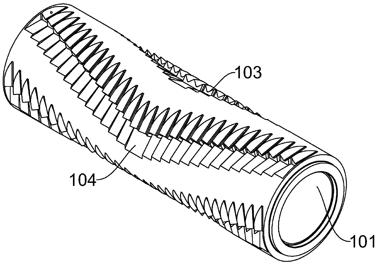
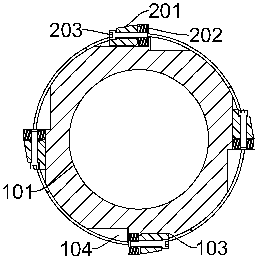
[0023] refer to Figure 1~3 , this embodiment discloses a cutter shaft structure, including a cutter shaft main body 101, the cutt...


PUM


Abstract

The invention discloses a cutter shaft structure. The cutter shaft structure comprises a cutter shaft main body 101, wherein the cutter shaft main body 101 is provided with a cylindrical surface, a plurality of cutter granules 202 arranged in the axial direction of the cutter shaft main body 101 are arranged on the cylindrical surface, every two adjacent cutter granules 202 are tightly attached to each other, and therefore no interval exists between teach two adjacent cutter granules 202, and furthermore compared with a sparse arrangement distribution mode, the larger quantity of the cutter granules 202 are arranged on the cutter shaft main body by adopting the attaching arrangement mode so as to improve cutting efficiency. Additionally, the invention further provides a single shaft crusher. The single shaft crusher comprises a cutter shaft and a stationary cutter 102 which cooperates with the cutter shaft for cutting, wherein the cutter shaft is set to be of the above cutter shaft structure. By rotating a crushing blade towards the stationary cutter 102 and then performing cutting work under cooperation of the crushing blade and the stationary cutter 102, the single shaft crusher greatly improves cutting speed and cutting efficiency, and can meet high yield and low cost requirements of solid waste well by combining with beneficial effects of the above cutter shaft structure.

Description

technical field [0001] The invention belongs to the technical field of crushers, and in particular relates to a cutter shaft structure and a single-shaft crusher adopting the cutter shaft structure. Background technique [0002] With the rapid development of our country's society, economy and industry over the years, the amount of solid waste generated has also become larger and larger. In the process of processing a wide variety of solid waste according to the principle of "harmless, resourceful, and reduced", the single-shaft crusher has uniform crushing size, can control the discharge size through the screen, and has short maintenance time. And other advantages, more and more widely used in solid waste shredding. However, the existing single-shaft crushers have the problems of low cutting and discharging efficiency, fast tool wear and high operating costs. The protruding height of the grains is low, which further leads to insufficient cutting capacity, resulting in low ...

Claims


Application Information

Patent Timeline
IPC IPC(8): B02C18/18
CPCB02C18/18
Inventor 吕文星郭华全
Owner HARDEN SHREDDER TECH
Learn More