Test work pipe vice transferring device

A transfer device and work tube technology, applied in the directions of transportation and packaging, multi-axis trolleys, trolleys, etc., can solve the problems of increased disassembly time and transportation costs, high labor intensity of hydraulic oil pipe clamps, low work efficiency, etc., and achieve convenient transportation. , The overall structure is reasonable, the effect of reducing transportation costs

Inactive Publication Date: 2019-09-20
张希录
7 Cites 0 Cited by

AI-Extracted Technical Summary

Problems solved by technology

[0002] In the use of pipe wrench in oilfield testing operations, the most commonly used is the hydraulic oil pipe wrench. The oil hydraulic pipe wrench is one of the wellhead mechanized equipment in the process of drilling and workover. It completes the tightening and unloading of the oil pipe. The traditional When installing the hydraulic oil pipe tong, it depends on the wire rope to hang from the lower part of the crane. When the hydra...

Method used

The hydraulic oil pipe wrench is directly installed on the pipe wrench fixed mount 06, avoiding the use of steel wire rope hoisting to solve the potential safety hazards in the use of the oil pipe wrench, making the overall structure more reasonable, while the bottom of the pipe wrench transfer vehicle 01 has universal wheels 03, It is convenient for transportatio...

Abstract

The invention discloses a test work pipe vice transferring device, which comprises a pipe vice transferring vehicle, tool storage drawers, universal wheels, an air cylinder, a fixing supporting frame, a pipe vice fixing frame, an X-shaped supporting frame and an oblique supporting plate. The multiple tool storage drawers are connected into the pipe vice transferring vehicle and slide in the pipe vice transferring vehicle; the bottom of the pipe vice transferring vehicle is connected with the multiple universal wheels, and the top of the pipe vice transferring vehicle is connected with a plurality of supporting vertical columns which are evenly distributed at the top of the pipe vice transferring vehicle; the tops of the supporting vertical columns are connected with a fixing supporting border, and third sliding grooves are symmetrically formed in the two sides of the fixing supporting border; the upper part of the fixing supporting border is connected with the fixing supporting frame which slides on the fixing supporting border, and the left side of the fixing supporting frame is connected with the air cylinder; and the lower part of the air cylinder is connected with the pipe vice transferring vehicle, and a plurality of positioning connection seats are arranged on the lower part of the pipe vice fixing frame.

Application Domain

Hand carts with multiple axes

Technology Topic

Internal connectionSupport plane +1

Image

  • Test work pipe vice transferring device
  • Test work pipe vice transferring device
  • Test work pipe vice transferring device

Examples

  • Experimental program(1)

Example Embodiment

[0019] Below according to accompanying drawing and embodiment the present invention will be described in further detail:
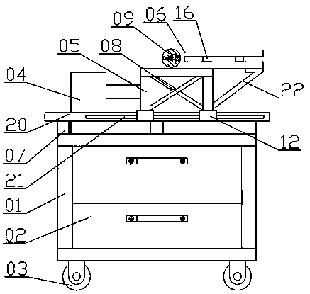
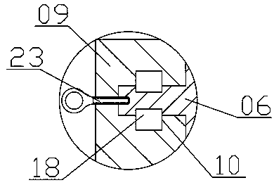
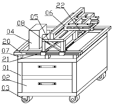
[0020] A pipe wrench transfer device for testing work, including a pipe wrench transfer car 01, a tool storage drawer 02, a universal wheel 03, a cylinder 04, a fixed support frame 05, a pipe wrench fixing frame 06, an X-shaped support frame 08, and an inclined support plate 22 The pipe wrench transfer vehicle 01 is internally connected with a plurality of tool storage drawers 02, the tool storage drawer 02 slides in the pipe wrench transfer vehicle 01, the bottom of the pipe wrench transfer vehicle 01 is connected with multiple universal wheels 03, and the pipe wrench transfer vehicle 01 The top of 01 is connected with a plurality of support columns 07, and the support columns 07 are evenly distributed on the top of the wrench transfer vehicle 01, and the top of the support column 07 is connected with a fixed support frame 20, and the fixed support frame 20 has No. 3 chute 21 on both sides. The No. 3 chute 21 is arranged symmetrically, the upper part of the fixed support frame 20 is connected to the fixed support frame 05, and the fixed support frame 05 slides on the fixed support frame 20, the left side of the fixed support frame 05 is connected to the cylinder 04, and the lower part of the cylinder 04 is connected to The pipe wrench transfer car 01, the lower part of the pipe wrench fixing frame 06 has a plurality of positioning connection seats 12, and the inside of the positioning connection seat 12 has a No. 3 protrusion 13, and the No. 3 protrusion 13 is adapted to the No. 3 chute 21, The No. 3 protrusion 13 is connected to the No. 3 chute 21, and the No. 3 protrusion 13 slides in the No. 3 chute 21. Both sides of the fixed support frame 05 are connected to the X-shaped support frame 08, and the upper part of the fixed support frame 05 has a No. 1 slide rail 09 .
[0021] The No. 1 slide rail 09 has a No. 1 chute 10 inside, the right side of the fixed support frame 05 has a No. 2 chute 11, the two sides of the load-bearing support frame 14 are connected to the fixed support frame 05, and the load-bearing support frame 14 has a No. 4 chute inside 15. The upper part of the fixed support frame 05 is connected to the pipe wrench fixed frame 06, and the pipe wrench fixed frame 06 slides on the fixed support frame 05.
[0022] The left side of the wrench fixing frame 06 has a roller 18, the roller 18 is compatible with the No. 1 chute 10, the roller 18 is connected to the No. 1 chute 10 through the ring screw 23, and the roller 18 slides in the No. 1 chute 10 , The lower part of the pipe wrench holder 06 has two No. 2 projections 17 .
[0023] The No. 2 protrusion 17 is adapted to the No. 2 chute 11, the No. 2 protrusion 17 is connected to the No. 2 chute 11, and the No. 2 protrusion 17 slides in the No. 2 chute 11. The upper part of the pipe wrench holder 06 has multiple A pipe wrench is fixed threaded hole 19, and the upper part of the pipe wrench fixing frame 06 is connected with a hydraulic oil pipe wrench.
[0024] The pipe wrench fixing frame 06 is internally connected with two positioning support plates 16, the lower part of the positioning support plate 16 is connected with the fixed support frame 05, and the positioning support plate 16 slides on the fixed support frame 05, and the lower part of the pipe wrench fixing frame 06 is connected with two inclined Support plate 22.
[0025] The inclined support plate 22 is arranged symmetrically, and the bottom of the inclined support plate 22 has a No. 4 protrusion 24. The No. 4 protrusion 24 is adapted to the No. 4 chute 15, and the No. 4 protrusion 24 is connected to the No. 4 chute 15, and No. projection 24 slides in No. four chute 15.
[0026] The hydraulic oil pipe wrench is directly installed on the pipe wrench fixing frame 06, avoiding the use of wire rope hoisting to solve the safety hazards existing in the use of the oil pipe wrench, making the overall structure more reasonable. It greatly saves the time of transporting the hydraulic oil pipe wrench, reduces the transportation cost, and makes the overall structure more reasonable. At the same time, the use of cylinder 04 to push the hydraulic oil pipe wrench reduces the labor intensity of workers, improves work efficiency, and makes the overall structure more reasonable.

PUM

no PUM

Description & Claims & Application Information

We can also present the details of the Description, Claims and Application information to help users get a comprehensive understanding of the technical details of the patent, such as background art, summary of invention, brief description of drawings, description of embodiments, and other original content. On the other hand, users can also determine the specific scope of protection of the technology through the list of claims; as well as understand the changes in the life cycle of the technology with the presentation of the patent timeline. Login to view more.

Similar technology patents

Load bearing member for wood structure building

ActiveCN112049244AThe overall structure is reasonableConstruction time is short
Owner:DALI UNIV

Water pump type defecation and gut purge device

InactiveCN103157151AThe overall structure is reasonableEasy to operate
Owner:沈挺

Mobile payment system based on electronic scale

InactiveCN113643488AThe overall structure is reasonableReduce the cumbersomeness of operation
Owner:韦颂东

Pressing machine for riveting rivets of telescopic connecting rod of intelligent clothes hanger

PendingCN114309433AThe overall structure is reasonablehigh degree of automation
Owner:浙江方合智能科技有限公司

Lumbar vertebra real-time monitoring device and real-time monitoring method

ActiveCN113243908AThe overall structure is reasonableThe overall structure is compact
Owner:广州中医药大学深圳医院

Classification and recommendation of technical efficacy words

  • easy to transport
  • The overall structure is reasonable

X-shaped self-heat insulating building block

InactiveCN102345339Aeasy to transportEasy to mold
Owner:李精华

Internal curing material of high-performance concrete and preparation method thereof

InactiveCN102390951AEasy to transport and useeasy to transport
Owner:RAILWAY ENG RES INST CHINA ACADEMY OF RAILWAY SCI

Support frame of adjustable suspension scaffold

Owner:江苏金土木建设集团华顺工程有限公司

Prefabricated modular tower

InactiveCN101163843Areduce weighteasy to transport
Owner:STRUCTURAL CONCRETE & STEEL

Hydraulic steering four-wheel drive axle of plant protection machine

InactiveCN104163199AThe overall structure is reasonableCompact and beautiful appearance
Owner:QINGZHOU MAITE AXLE MFG

Cylindrical roller bearing with integrated solid copper retainer

PendingCN110454502AThe overall structure is reasonableincrease speed
Owner:XIANGYANG AUTOMOBILE BEARING CO LTD

Special intelligent patrolling system for biological reaction pool of sewage treatment plant

ActiveCN110009762AThe overall structure is reasonablePractical
Owner:SHANGHAI MUNICIPAL ENG DESIGN INST GRP

Shuttlecock lifting and clamping assembly and serving machine

PendingCN111514567AThe overall structure is reasonableThe overall structure is compact
Owner:艾迪宝体育用品(深圳)有限公司

Full-automatic direct drinking water supply system for building

InactiveCN104652535AThe overall structure is reasonablelow cost
Owner:WENZHOU HAIDENENG ENVIRONMENTAL PROTECTION EQUIP & TECH
Why Eureka
Try Eureka