
Plate feeding mechanism of plate feeding machine and operation method of plate feeding mechanism of plate feeding machine

A technology of trigger and frame, which is applied in the field of loading mechanism of loading machine, can solve problems affecting the loading process, affecting sheet material transportation, sheet material damage, etc., and achieves the effect of wide application range

Active Publication Date: 2019-09-20
安徽天通精电新科技有限公司
View PDF5 Cites 6 Cited by
  • Summary
  • Abstract
  • Description
  • Claims
  • Application Information

AI Technical Summary

Problems solved by technology

[0003] During the working process of the upper plate mechanism of the existing plate loading machine, the heights of the stacked plate parts and the docking part of the production line are fixed. The height is determined before production; at the same time, after the board is loaded, the accumulated board is easy to be inclined and uneven during the conveying process, which will affect the subsequent conveying of the board one by one, and the piled up board will be spilled during the transportation, causing damage to the board The whole loading process

Method used


Image

  • Plate feeding mechanism of plate feeding machine and operation method of plate feeding mechanism of plate feeding machine
  • Plate feeding mechanism of plate feeding machine and operation method of plate feeding mechanism of plate feeding machine
  • Plate feeding mechanism of plate feeding machine and operation method of plate feeding mechanism of plate feeding machine

Examples


Embodiment Construction

[0027] The technical solutions of the present invention will be clearly and completely described below in conjunction with the embodiments. Apparently, the described embodiments are only some of the embodiments of the present invention, not all of them. Based on the embodiments of the present invention, all other embodiments obtained by persons of ordinary skill in the art without creative efforts fall within the protection scope of the present invention.

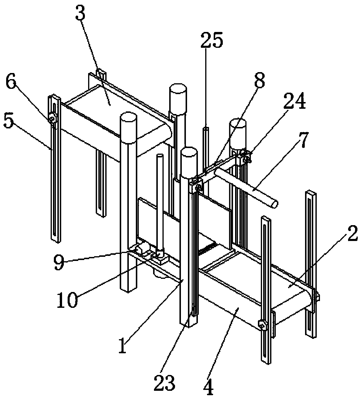
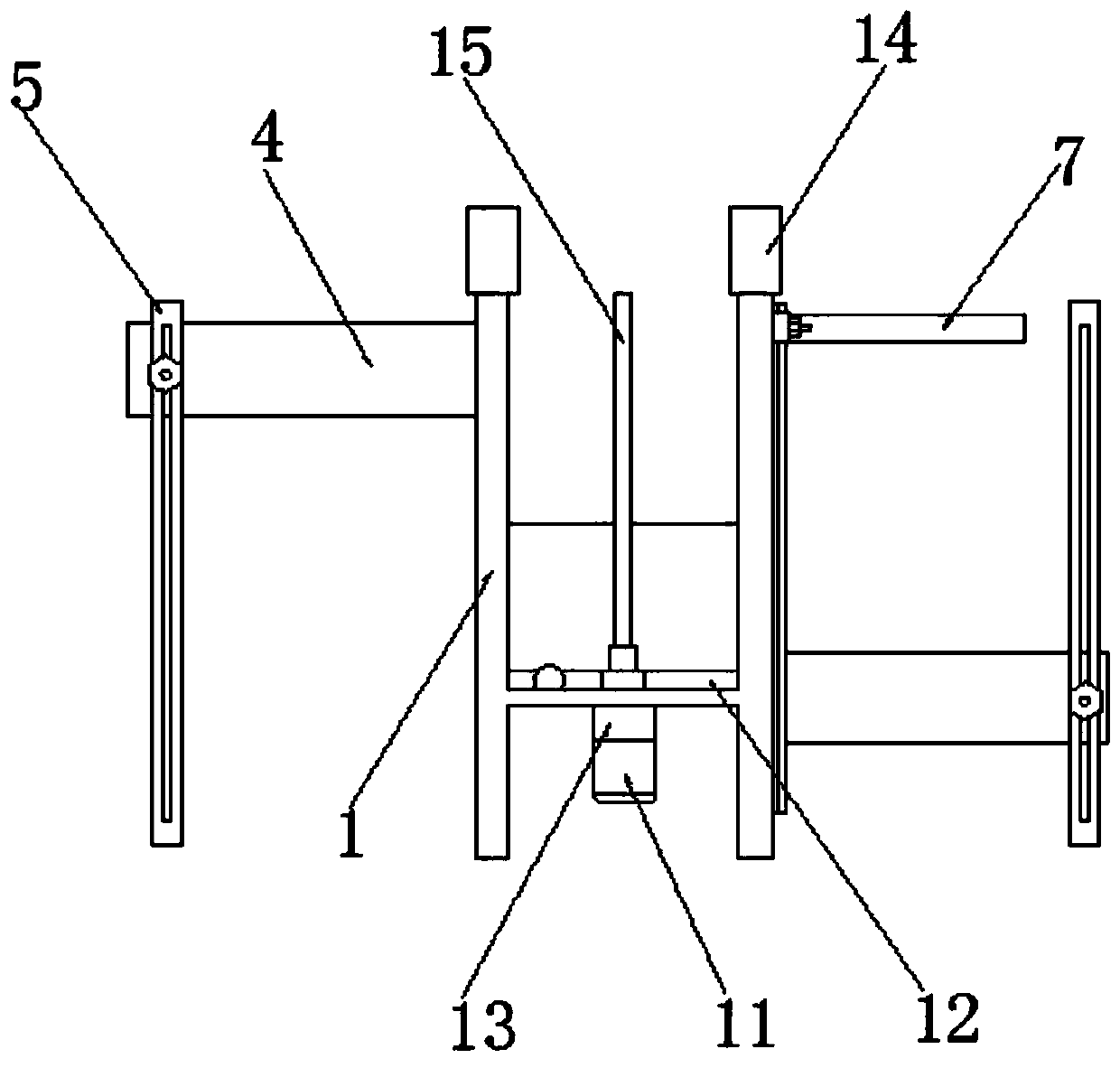
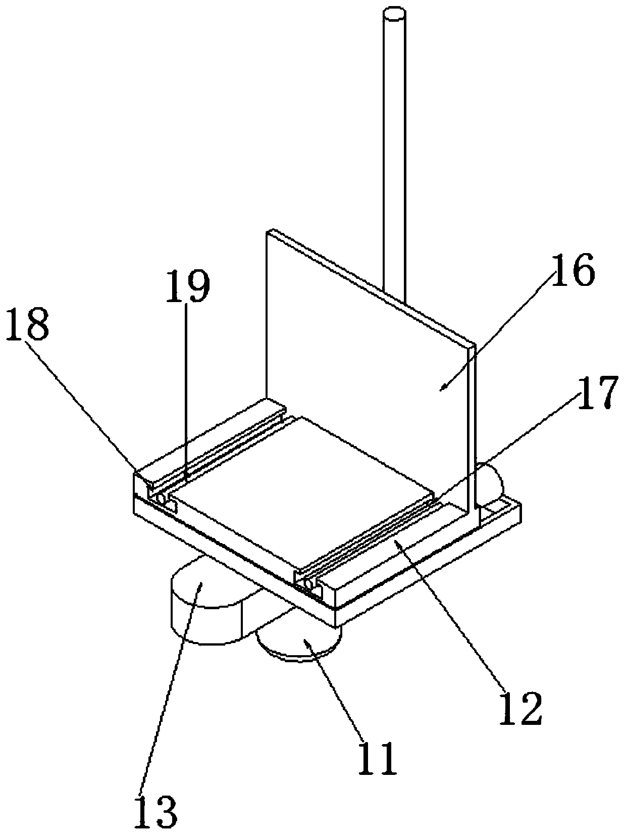
[0028] see Figure 1-4 As shown, a loading mechanism of a loading machine includes a frame 1, a first conveyor belt 2, a second conveyor belt 3, a first servo motor 9, a second servo motor 11, a loading plate 12 and a third servo motor 14 , the first conveyor belt 2 is installed on one side of the frame 1, and the second conveyor belt 3 is installed on the other side of the frame 1. Baffles 4 are installed on both sides of the first conveyor belt 2 and the second conveyor belt 3, and the baffles 4 on both sides are far away...


PUM


Abstract

The invention discloses a plate feeding mechanism of a plate feeding machine. A rack, a first conveying belt, a second conveying belt, a first servo motor, a second servo motor, a material carrying plate and a third servo motor are included; the first conveying belt is installed on one side of the rack, and the second conveying belt is installed on the other side of the rack; baffles are installed on the two sides of the first conveying belt and the second conveying belt; the sides, away from the rack end, of the baffles on the two sides are provided with supporting legs; the bottom center position of the rack is provided with a conveying box; the bottom center position of the conveying box is provided with the second servo motor; and the material carrying plate is installed above the rack. According to the plate feeding mechanism of the plate feeding machine, the heights of the conveying belts on the two sides can be adjusted according to an actual production line and the using condition, and the application range is wide; plate materials of the first conveying belt are subjected to reshaping operation through clamping plates on the two sides, it is guaranteed that accumulated plate materials located on the plate carrying plate are flat all the time, the plate materials are conveniently conveyed onto the production line subsequently one by one, and the situation that the accumulated plate materials are scattered in the plate feeding process is avoided.

Description

technical field [0001] The invention relates to the field of board loading devices, in particular to a board loading mechanism of a board loading machine and an operation method thereof. Background technique [0002] The loading machine transfers the stacked sheets on one side to the production line one by one. After all the stacked sheets are transferred, the stacked sheets are put back into the side of the loading machine to complete the cycle work. [0003] During the working process of the upper plate mechanism of the existing plate loading machine, the heights of the stacked plate parts and the docking part of the production line are fixed. The height is determined before production; at the same time, after the board is loaded, the accumulated board is easy to be inclined and uneven during the conveying process, which will affect the subsequent conveying of the board one by one, and the piled up board will be spilled during the transportation, causing damage to the boar...

Claims


Application Information

Patent Timeline
IPC IPC(8): B65G15/56B65G21/12B65G21/20B65G23/22B65G47/82B65G47/52
CPCB65G15/56B65G21/12B65G21/2054B65G23/22B65G47/52B65G47/82B65G2201/022
Inventor 姜传明贾亚飞罗西安
Owner 安徽天通精电新科技有限公司
Learn More