Ball screw type electric cylinder

A ball screw and electric cylinder technology, applied in the field of electric lifting mechanism and ball screw electric cylinder, can solve the problems of poor positioning accuracy, easy dust accumulation and water leakage, poor rainproof and dustproof effect, etc., and achieves a simple and reliable structure. , Good dustproof and rainproof functions, high transmission efficiency and high positioning accuracy

Active Publication Date: 2019-09-20
XIAN HUA OU PRECISION MACHINERY
View PDF11 Cites 6 Cited by
  • Summary
  • Abstract
  • Description
  • Claims
  • Application Information

AI Technical Summary

Problems solved by technology

Hydraulic lifting equipment and pneumatic lifting equipment need to be equipped with hydraulic systems and compressors, which have disadvantages such as large equipment structure, heavy weight, small bearing capacity, difficult self-locking, inaccurate transmission, and restrictions on use by many environmental conditions; the existing Although the trapezoidal electric cylinder lifting equipment has good self-locking performance, it has low efficiency, high energy consumption, large clearance, and poor positioning accuracy.
In addition, the existing trapezoidal electric cylinder lifting equipment adopts a lifting structure with a small upper part and a larger lower part, that is, the sliding sleeve as the lifting component is arranged inside the outer sleeve as the supporting component, and the protruding part on the upper part decreases step by step. This structure is easy to accumulate dust and leak water between the joints of the lifting components, and the rainproof and dustproof effect is poor, so it is not suitable for use in open air and field workplaces

Method used


Image

  • Ball screw type electric cylinder

Examples


Embodiment Construction

[0011] The content of the present invention will be further described below in conjunction with the accompanying drawings, but the actual production structure of the present invention is not limited to the following embodiments.

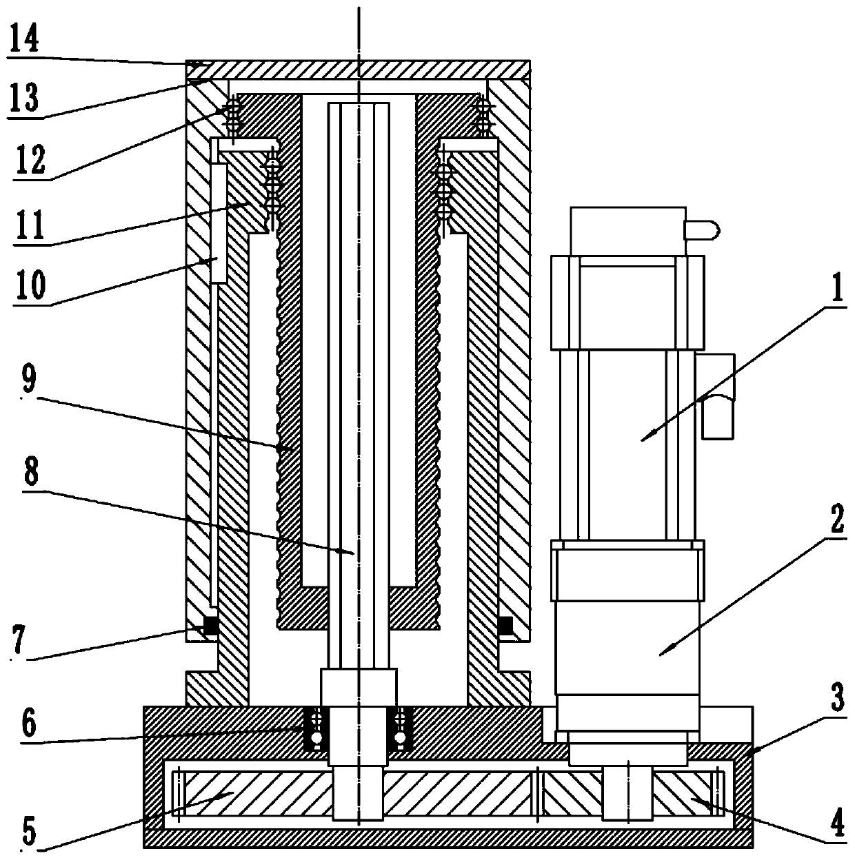
[0012] Referring to the accompanying drawings, the ball screw electric cylinder of the present invention consists of a power transmission box 3 and a motor 1, a reducer 2, a driving gear 4, a driven gear 5, a transmission shaft 8, and a ball screw arranged on the power transmission box 3. Members such as bar 9, sleeve nut 11, outer sliding sleeve 13 and upper top plate 14 are formed. The motor 1 and the reducer 2 form a power device, and the meshingly connected driving gear 4 and driven gear 5 form a gear pair transmission. The axle bar of transmission shaft 8 is a square rod, is installed on the power transmission case 3 by bearing 6, and the lower end of transmission shaft 8 is connected with the wheel center of moving gear 5, and bearing 6 plays a...


PUM


Abstract

The invention relates to a ball screw type electric cylinder of which a transmission element is a ball screw pair. The ball screw type electric cylinder comprises a power transmission box, a rectangular rod transmission shaft, a hollow ball screw, a sleeve nut and an outer sliding sleeve, wherein the power transmission box is provided with a power device and a transmission device; the rectangular rod transmission shaft is vertically arranged on the power transmission box; the hollow ball screw, the sleeve nut and the outer sliding sleeve sequentially coaxially sleeve the transmission shaft from inside to outside; the transmission shaft and the ball screw can slide relative to each other; the sleeve nut and the ball screw form the ball screw pair; the upper end of the inner pore wall of the outer sliding sleeve is connected to the upper end of the outer wall of the ball screw through a supporting bearing; the ball screw can be rotated relative to the outer sliding sleeve; the outer sliding sleeve and the sleeve nut can up and down linearly slide through guide keys; and an upper top plate is mounted on the top part of the outer sliding sleeve. When in work, the power device is capable of driving the transmission shaft to rotate through a transmission device; the transmission shaft in rotating drives the ball screw to rotate; and the ball screw in rotating drives the outer sliding sleeve to up and down move, and thus the function of lifting up and down working load is achieved.

Description

technical field [0001] The invention belongs to the technical field of electric lifting mechanisms, and relates to a lifting mechanism mainly used in field lifting operations, in particular to a ball screw electric cylinder using a ball screw pair as a transmission element. Background technique [0002] At present, in the lifting equipment work place, according to the needs, the objects to be lifted are often lifted to different heights for work. In the traditional lifting technology, hydraulic lifting equipment, pneumatic lifting equipment and trapezoidal electric cylinder are generally used to drive the lifting equipment. Hydraulic lifting equipment and pneumatic lifting equipment need to be equipped with hydraulic systems and compressors, which have disadvantages such as large equipment structure, heavy weight, small bearing capacity, difficult self-locking, inaccurate transmission, and restrictions on use by many environmental conditions; the existing Although the trape...

Claims


Application Information

Patent Timeline
IPC IPC(8): B66F3/08B66F3/44
CPCB66F3/08B66F3/44
Inventor 樊延都陈寂
Owner XIAN HUA OU PRECISION MACHINERY
Why Eureka
Try Eureka