A construction method for aerial connection of steel pipe arch rib segments

A construction method and technology of steel pipe arch ribs, applied in arch bridges, buildings, bridge construction, etc., can solve the problems that locking devices cannot be dismantled and reused, flange plate 05 deflected bolts are installed and constructed, and concrete jacking construction is blocked, etc. Achieve the effect of convenient disassembly and reuse, strong applicability and economy, and improve construction efficiency

Active Publication Date: 2020-09-22
CHINA RAILWAY ERYUAN ENG GRP CO LTD +1
View PDF7 Cites 0 Cited by
  • Summary
  • Abstract
  • Description
  • Claims
  • Application Information

AI Technical Summary

Problems solved by technology

[0006] 1. The flange 05 and the bolt-to-hole construction method are used to locate the arch rib segment 01 hoisted in the air. Due to the high requirements for the installation accuracy of the holes, the positioning is difficult and the construction efficiency is low;
[0007] 2. During the installation and construction of the locking device, both ends of the rib plate 06 are connected by welding. The welding construction will easily lead to the deflection of the flange plate 05 and affect the installation and construction of the bolts. The residual stress of welding will also lead to stress concentration and uneven force on the steel pipe section;
[0008] 3. The locking device is installed inside the steel pipe. After the butt sleeve 07 is embedded, the locking device cannot be removed and reused, which not only increases the construction auxiliary cost, but also prevents the concrete jacking construction in the steel pipe

Method used


Image

  • A construction method for aerial connection of steel pipe arch rib segments
  • A construction method for aerial connection of steel pipe arch rib segments
  • A construction method for aerial connection of steel pipe arch rib segments

Examples


Embodiment

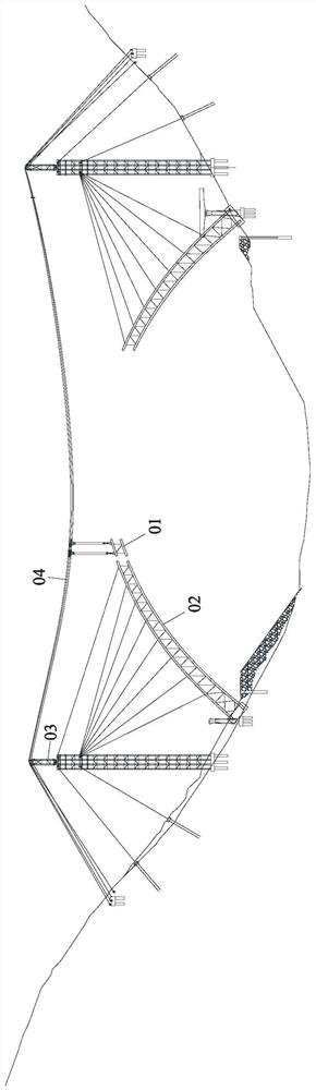
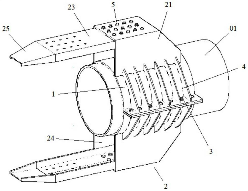
[0048] Such as Figure 3-8 As shown, a construction method for aerial connection of a steel pipe arch rib segment according to the present invention comprises the following steps:

[0049] A. If Figure 3-6 As shown, two semi-circular hoop steel plates 1 of the same size and shape are installed at the end of the steel pipe of the arch rib section 01, and the contact surface between the hoop steel plate 1 and the steel pipe of the arch rib section 01 Anti-skid paint is sprayed on the contact surface with the installed arch rib 02 steel pipe;

[0050] B. Ear plates are provided at both ends of each hoop steel plate 1, and the lug plates after the cooperation of the two hoop steel plates 1 are bolted together by several first bolts 3, so that the two hoop steel plates 1 embrace Close to the circumference of the steel pipe of the arch rib segment 01;

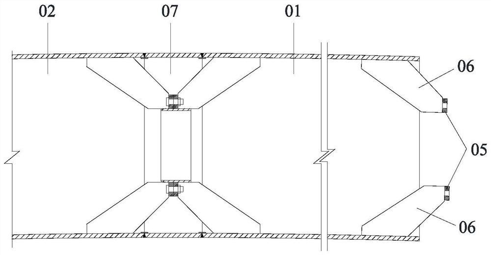
[0051] Such as image 3 As shown, the steel pipe of the arch rib segment 01 needs to be connected with the first limit seat 21...


PUM


Abstract

The invention discloses a construction method for aerial connection of steel tube arc rib segments. The construction method comprises the following steps that A, two semicircular hoop steel plates which can be connected in a bolted manner are installed at the end of each arc rib segment steel tube, each hoop steel plate is provided with a first limiting seat, a second limiting seat and stiffening rib plates; B, each first limiting seat is connected with a guide limiting bar, each second limiting seat is provided with a limiting groove, and each guide limiting bar is matched with the limiting groove; C, one arc rib segment steel tube is lifted to an aerial splicing position, the position of the arc rib segment steel tube is adjusted to enable the guide limiting bar on the arc rib section to be inserted into the limiting groove of the installed arc rib steel tube, the arc rib segment steel tube is moved in the length direction of the guide limiting bar to be aligned with the installed arc rib steel tube and abut against the installed arc rib steel tube, and the guide limiting bar on the arc rib segment and the limiting groove on the installed arc rib steel tube are relatively locked; D, the arc rib segment steel tube and the installed arc rib steel tube are in butt joint and welded into a whole. The construction method is simple in process, convenient to implement and good in effect and has quite high applicability and economical efficiency.

Description

technical field [0001] The invention relates to the field of bridge construction, in particular to a construction method for aerial connection of steel pipe arch rib segments. Background technique [0002] The cable hoisting construction method is one of the main construction methods of concrete filled steel tube arch bridges. figure 1 As shown, it divides the arch rib into several arch rib segments 01 along the longitudinal direction of the bridge, and transports the arch rib segment 01 to the installation position in the air through the hoisting tower 03 and the cable 04 traction, and then welds it to the installed arch rib 02 structurally. [0003] In order to ensure the accuracy and quality of the aerial welding construction of hoisting arch rib segments, it is necessary to temporarily lock it to the installed arch rib structure. It also affects the pouring strength and quality of the concrete in the steel pipe for jacking construction. [0004] The current constructi...

Claims


Application Information

Patent Timeline
Patent Type & Authority Patents(China)
IPC IPC(8): E01D21/10E01D4/00E01D101/26
CPCE01D4/00E01D21/10E01D2101/26
Inventor 刘忠平陈国栋陈克坚罗实张安宇
Owner CHINA RAILWAY ERYUAN ENG GRP CO LTD
Why Eureka
Try Eureka