Reversing brake device of DC electric tool switch and DC electric tool switch

A brake device and electric tool technology, which is applied in the field of electric switches, can solve problems such as arcing and sparking of reversing shrapnel, and achieve the effect of improving service life

Pending Publication Date: 2019-09-20
KEDU ELECTRIC CO LTD
View PDF1 Cites 0 Cited by
  • Summary
  • Abstract
  • Description
  • Claims
  • Application Information

AI Technical Summary

Problems solved by technology

[0006] Therefore, the technical problem to be solved by the present invention is to overcome the DC power tool switch in the prior art. When commutating, the instantaneous armature current generated by the motor due to inertial rotation will pass through the reversing device, which may cause the reversing device to The reversing shrapnel produces the defect of arcing sparks, so as to provide a reversing brake device that can release the armature current generated by the motor without passing through the reversing device

Method used


Image

  • Reversing brake device of DC electric tool switch and DC electric tool switch
  • Reversing brake device of DC electric tool switch and DC electric tool switch
  • Reversing brake device of DC electric tool switch and DC electric tool switch

Examples


Embodiment 1

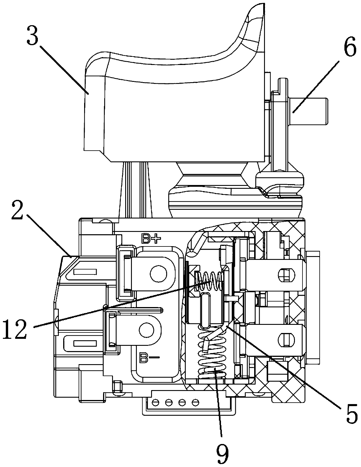
[0067] This embodiment provides a reversing braking device 1, such as image 3 As shown, it includes a housing 2 , a switch button 3 , a movable rod 24 , a reversing device 4 and a brake moving contact 5 . The reversing device 4 may have the same structure as the prior art, that is, by rotating the reversing rod 6, the direction in which the current enters the motor 7 is switched, so that the forward and reverse directions of the motor 7 are switched.

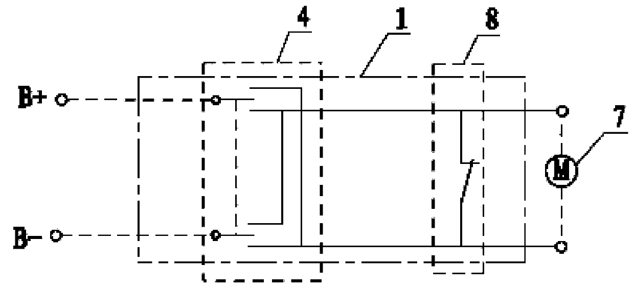
[0068] like figure 1 As shown, in the circuit schematic diagram of the reversing braking device, the reversing device 4 is connected between the motor 7 and the DC power supply, and the direction of the current entering the motor 7 is changed by switching. The two electrical connection ends of the braking device 8 are directly electrically connected to both ends of the motor 7 respectively, and the braking device 8 is in a closed state and forms a closed loop with the motor 7 .

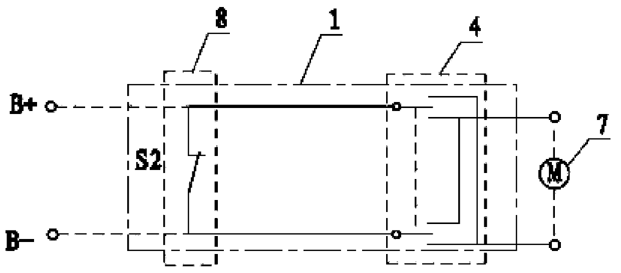
[0069] like figure 2 As shown, it is the cir...

Embodiment 2

[0079] This embodiment provides a reversing braking device 1, such as Figure 8 As shown, it includes a housing 2 , a switch button 3 , a movable rod 24 , a reversing device 4 and a brake moving contact 5 . Most of its structure is the same as that of the reversing brake device of the first embodiment, and the circuit principle of the reversing brake device is also the same as that of the first embodiment. The difference is that the brake moving contact 5 in this embodiment is slidably arranged in the switch housing 2 .

[0080] like Figure 9 As shown, the brake moving contact 5 of this embodiment includes: a first contact 13 , a second contact 21 and a connecting ring 22 . The first contact 13 is located on the top of the brake moving contact 5, and is used for electrical connection with the first contact point 10 when the brake device 8 is in the closed state; the second contact 21 is located on the brake moving contact The bottom of the head 5, when the brake device 8 i...

Embodiment 3

[0085] This embodiment provides a reversing braking device 1, such as Figure 15 As shown, it includes a casing 2 , a switch button 3 , a movable rod 24 , a reversing device 4 and a brake moving contact 5 . Most of its structure is the same as that of the reversing braking device of the first and second embodiments, and the circuit principle of the reversing braking device is also the same as that of the first and second embodiments. The braking contact 5 of this embodiment is also slidably arranged in the switch housing 2 as in the second embodiment, the difference lies in the shape of the braking contact 5 of this embodiment, and the matching with the braking contact 5 Other structures have been improved.

[0086] like Figure 16 As shown, the brake moving contact 5 of this embodiment includes: a first contact 13 , a second contact 21 and a connecting piece 25 . The first contact 13 is located on the top of the brake moving contact 5, and is used for electrical connection w...


PUM


Abstract

The invention provides a reversing brake device of a DC electric tool switch and the DC electric tool switch, and belongs to the technical field of an electric switch. The reversing brake device of the DC electric tool switch comprises a reversing device, which is connected between a motor and a DC power source, and is used for changing the direction of the current entering a motor by switching; and a brake device, wherein in a closed state, the two electrical connection ends of the brake device are directly and electrically connected to the two ends of the motor respectively to form a closed loop with the motor. According to the reversing brake device, when the reversing device carries out reversing switching, the brake device is in a closed state, and the brake device and the motor form the closed loop, so that larger instantaneous armature current generated during motor rotation can be consumed in time to prevent arc discharge of the reversing device during reversing switching, damage to the switch by sparks produced after arc discharge is prevented and service life of the switch is improved.

Description

technical field [0001] The invention relates to the technical field of electric switches, in particular to a reversing braking device of a DC power tool switch, and a DC power tool switch. Background technique [0002] The DC power tool switch, such as the switch of the electric drill, generally has a reversing device, and the direction of the DC power tool switch can be changed through the switching of the reversing device. [0003] For example, the DC power tool switch disclosed in Chinese patent document CN208368375 includes a button and a housing, and has a push rod, a moving contact and a static contact in the housing. The button is connected with the moving contact through the push rod, and then by pressing the button, the contact or disconnection between the moving contact and the static contact is controlled. The reversing dial handle assembly with forward and reverse function on the housing can contact the corresponding static contact piece on the housing by rotati...

Claims


Application Information

Patent Timeline
Patent Type & Authority Applications(China)
IPC IPC(8): H01H13/14H01H13/10H01H13/52H01H13/66
CPCH01H13/10H01H13/14H01H13/52H01H13/66
Inventor 郑春开李子平张勇
Owner KEDU ELECTRIC CO LTD
Why Eureka
Try Eureka