Axial force and displacement control mechanism

A technology of displacement control and axial force, applied in manufacturing tools, metal processing, metal processing equipment, etc., can solve the problems of low control precision, time-consuming and laborious, difficult to adapt to nuts, etc., and achieve high control precision and wide application range. Effect

Pending Publication Date: 2019-09-24
HEFEI HENGDAJIANGHAI PUMP IND CO LTD
View PDF0 Cites 0 Cited by
  • Summary
  • Abstract
  • Description
  • Claims
  • Application Information

AI Technical Summary

Problems solved by technology

The shaft nut is pre-tightened by hand in the empty space stage. This stage is free from axial resistance, and the manual operation is simple and fast. However, during the locking process of the shaft nut, it is subject to axial resistance. Manual screwing with lever tools is time-consuming and laborious. Ordinary hydraulic wrench has poor versatility, it is difficult to adapt to nuts of different specifications, and the control accuracy is low

Method used


Image

  • Axial force and displacement control mechanism
  • Axial force and displacement control mechanism
  • Axial force and displacement control mechanism

Examples


Embodiment 1

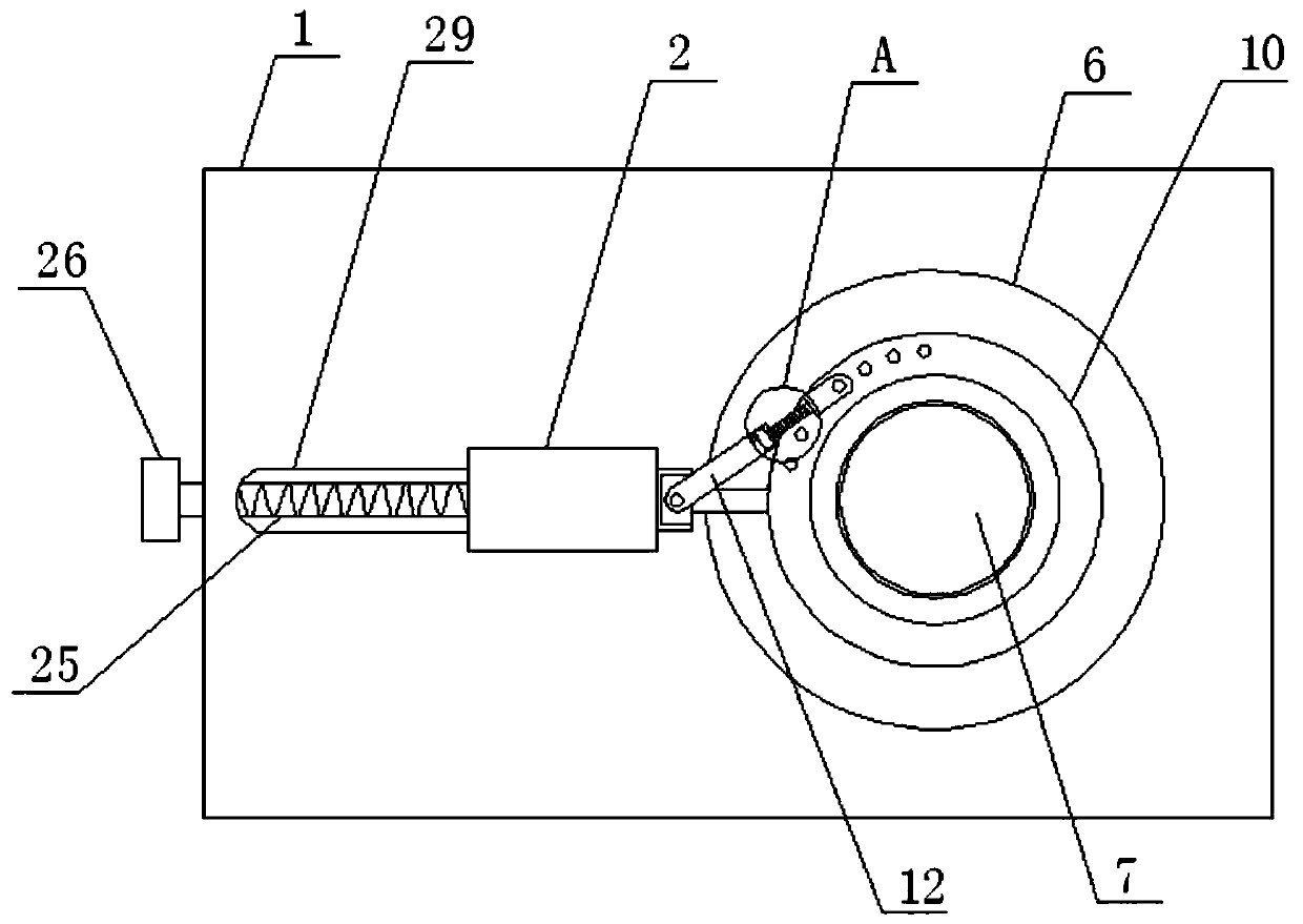
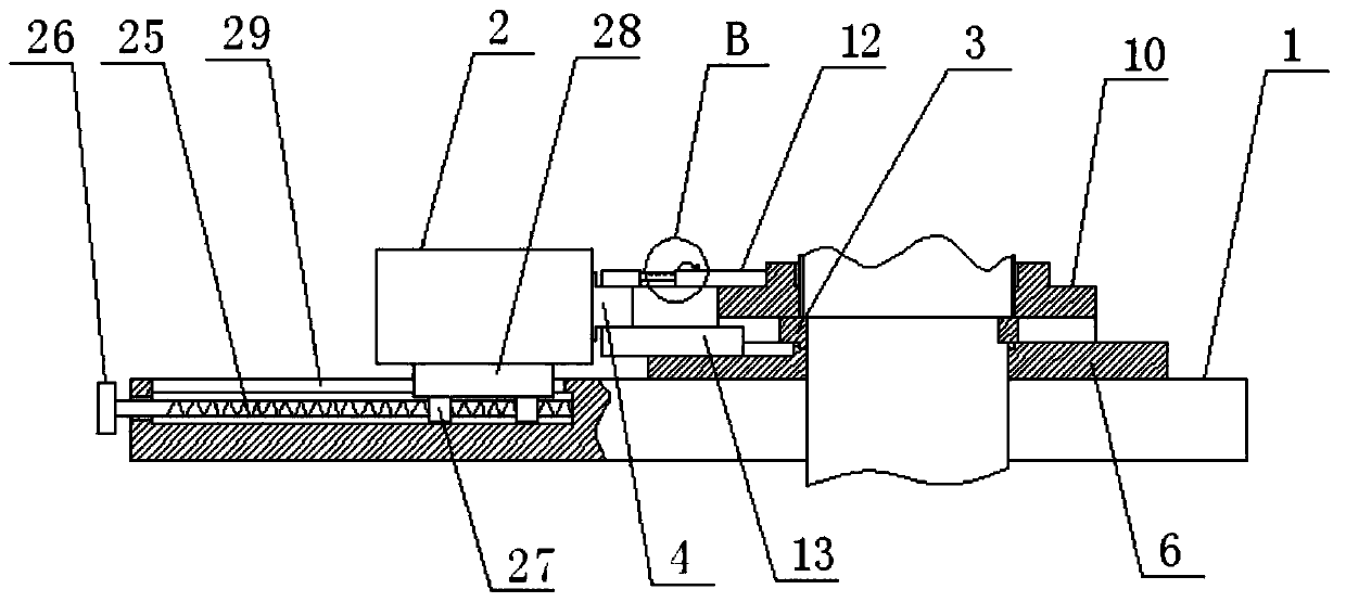
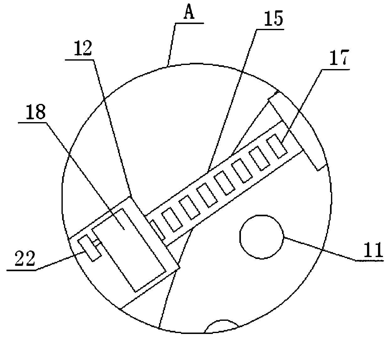
[0031] according to Figure 1-11 The axial force and displacement control mechanism shown includes a base 1 and a hydraulic cylinder 2. A fixed disc 3 is arranged on the top of the base 1. The hydraulic cylinder 2 includes a protruding rod 4. The fixed disc 3 The top surface is provided with a first positioning groove 5 near one side. By providing the first positioning groove 5, when the slider 13 is moved to a certain position, the slider 13 enters the inside of the first positioning groove 5, and the extension rod 4 is increased. The length of extension, the top of the fixed disc 3 is placed with a positioning disc 6, the center of the fixed disc 3 and the positioning disc 6 are provided with a transparent shaft hole 7, the shaft hole of the positioning disc 6 7 is provided with a keyway 8 inside, and the positioning disc 6 is fixed to the shaft by using a special positioning key for the shaft. A second positioning slot 9 is provided on one side of the positioning disc 6, an...


PUM


Abstract

The invention discloses an axial force and displacement control mechanism. The axial force and displacement control mechanism comprises a base and a hydraulic cylinder, a fixed disc is arranged on the top of the base, the hydraulic cylinder comprises an extension rod, a first positioning groove is formed in the position, close to one side, of the top surface of the fixed disc, a positioning disc is placed on the top of the fixed disc, through shaft holes are formed in the centers of the fixed disc and the positioning disc, a key groove is formed in the shaft hole of the positioning disc, a second positioning groove is formed in one side of the positioning disc, the top and the bottom of the second positioning groove communicate, a shaft nut is placed on the surface of the positioning disc, multiple thread holes are evenly formed in the surface of the shaft nut, and one end of an extension rod is arranged in a laterally-laying protrusion shape. Through hydraulic pressure and a connecting rod, the shaft nut is controlled to do crank sliding block motion, the high control precision is achieved, the position of the extension rod is subjected to fine adjustment, the axial force borne by the shaft nut can be conveniently controlled, and the control precision is high.

Description

technical field [0001] The invention relates to the technical field of shaft installation equipment, in particular to an axial force and displacement control mechanism. Background technique [0002] In industrial production, it is often necessary to control the axial displacement or axial force of parts. Generally, shaft nuts are used to apply axial force or axial displacement. The shaft nut is pre-tightened by hand in the empty space stage. This stage is free from axial resistance, and the manual operation is simple and fast. However, during the locking process of the shaft nut, it is subject to axial resistance. Manual screwing with lever tools is time-consuming and laborious. Ordinary hydraulic wrenches have poor versatility, are difficult to adapt to nuts of different specifications, and have low control precision. [0003] Therefore, it is necessary to invent an axial force and displacement control mechanism to solve the above problems. Contents of the invention [...

Claims


Application Information

Patent Timeline
IPC IPC(8): B23P19/00B25B27/00
CPCB23P19/00B25B27/00
Inventor 李星荚小健孙圣年
Owner HEFEI HENGDAJIANGHAI PUMP IND CO LTD
Why Eureka
Try Eureka