Lifting-clamping-type vacuum chuck clamp and use method thereof

A vacuum suction cup, clamping type technology, applied in the direction of chucks, manufacturing tools, manipulators, etc., can solve the problems of loss, easy damage, and inability to identify goods, and achieve the effect of reducing weight and improving efficiency

Pending Publication Date: 2019-09-24
SPEEDBOT ROBOTICS CO LTD
View PDF0 Cites 7 Cited by
  • Summary
  • Abstract
  • Description
  • Claims
  • Application Information

AI Technical Summary

Problems solved by technology

[0005] (1) The existing robot grippers are easy to damage the carton outer packaging and the sunken film packaging when the robot speed is too fast, and cann

Method used


Image

  • Lifting-clamping-type vacuum chuck clamp and use method thereof
  • Lifting-clamping-type vacuum chuck clamp and use method thereof
  • Lifting-clamping-type vacuum chuck clamp and use method thereof

Examples


Embodiment Construction

[0039] In order to further understand the content, features and effects of the present invention, the following examples are given, and detailed descriptions are given below with reference to the accompanying drawings.

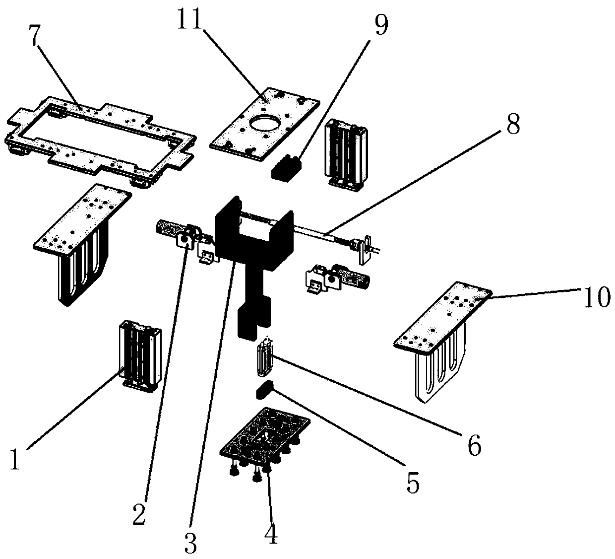
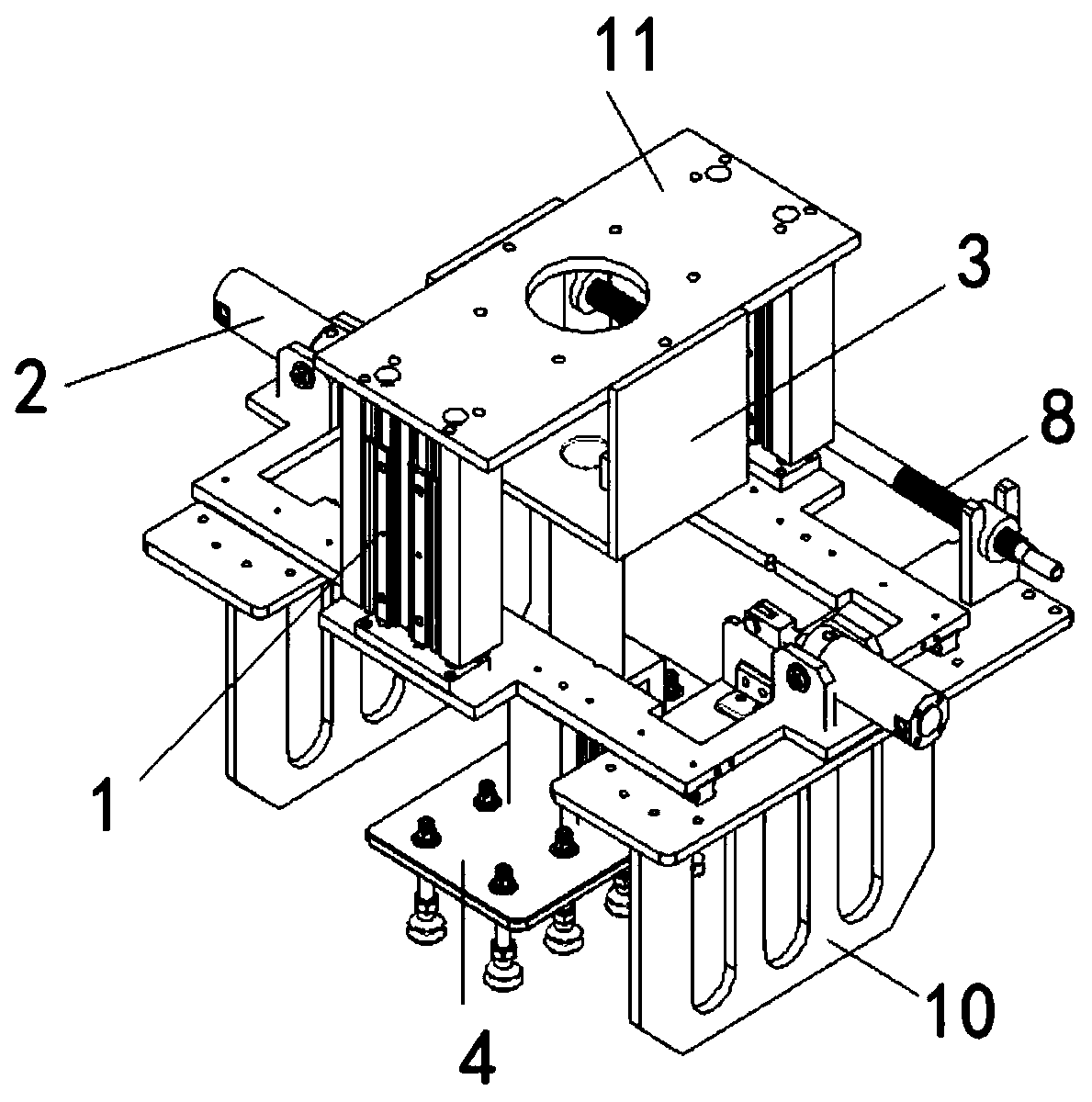
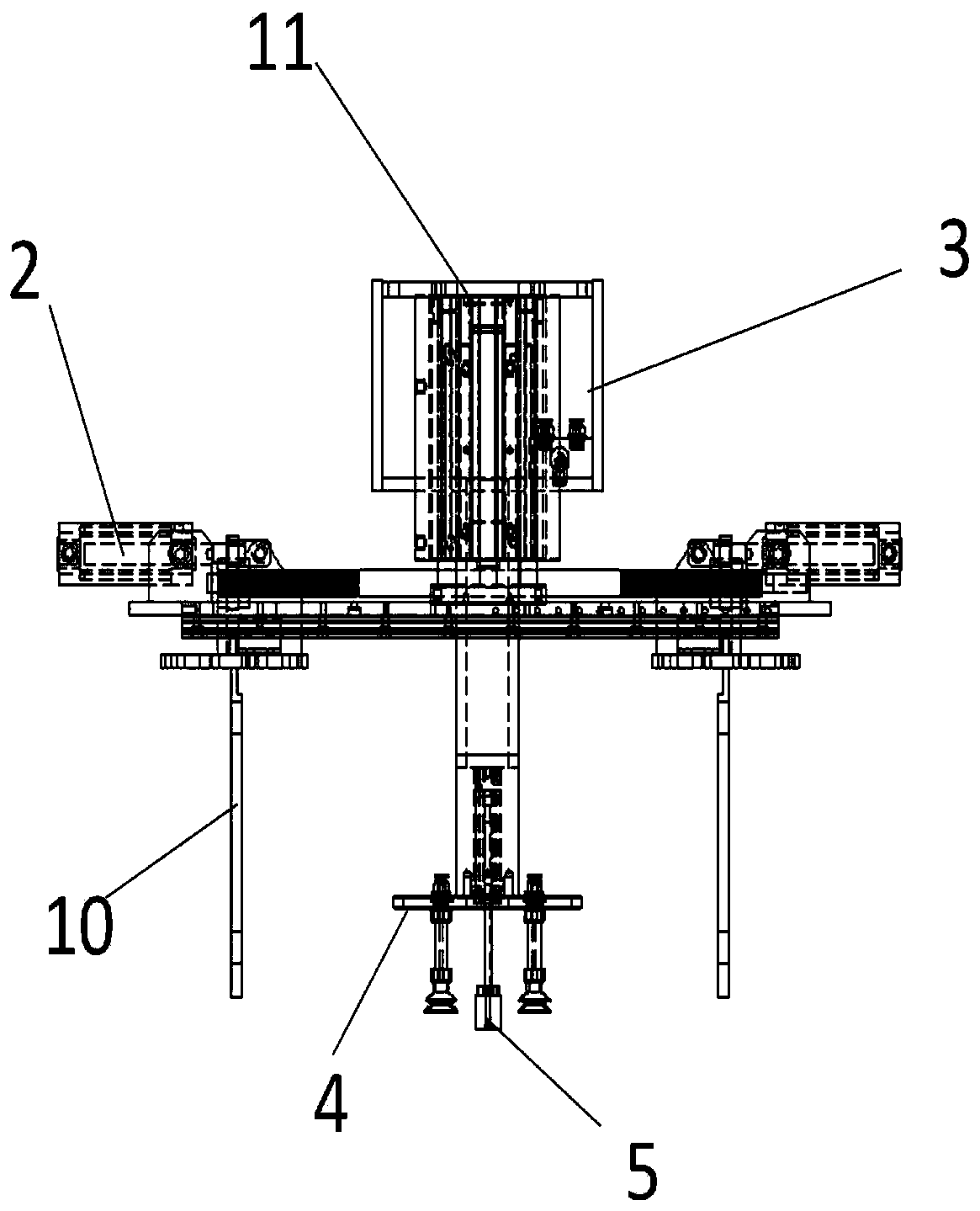
[0040] Such as Figure 1 to Figure 3 As shown, the lifting and clamping vacuum suction cup fixture provided by the embodiment of the present invention includes: a three-axis cylinder 1, a one-way cylinder 2, a mounting frame 3, a suction cup 4, a 3D camera 5, a camera three-axis cylinder 6, a rail frame 7, and a spring Rod 8, vacuum system related components 9, splint 10, clamp connection plate 11.

[0041] The middle of the mounting frame 3 is provided with a connecting pipe, and the upper and lower ends of the connecting pipe are welded with vertical mounting grooves. The lower end of the mounting frame 3 is fixed with a suction cup 4 by bolts; The lower sides of both ends are connected with a three-axis cylinder 1 by bolts, the lower end of the three-axis ...


PUM


Abstract

The invention belongs to the technical field of robot clamps and discloses a lifting-clamping-type vacuum chuck clamp and a use method thereof. The lifting-clamping-type vacuum chuck clamp is provided with a mounting frame; a chuck is fixed at the lower end of the mounting frame through bolts; a clamp connecting plate is fixed at the upper end of the mounting frame through bolts; the lower sides of the two ends of the clamp connecting plate are connected with triaxial cylinders through bolts; a guide rail frame is fixed at the lower ends of the three-axis cylinders through bolts; one-way air cylinders are fixed on the upper sides of the left and right ends of the guide rail frame through bolts; the lower ends of the output shafts of the two one-way air cylinders are connected with clamping plates through bolts; a triaxial camera cylinder is fixed in a mounting groove in the lower end of the mounting frame through bolts; the lower end of the output shaft of the triaxial camera cylinder is connected with a three-dimensional camera through bolts; and the three-dimensional camera penetrates through a rectangular through hole formed in the center of the chuck. According to the lifting-clamping-type vacuum chuck clamp, through the combined design of the air cylinder, the chuck and the clamping plates and the article recognition of the three-dimensional camera, the problems of incapability of cargo recognition and grabbing, damage and slow grabbing beat are solved.

Description

technical field [0001] The invention belongs to the technical field of robot fixtures, and in particular relates to a lifting and clamping vacuum suction cup fixture and a using method. Background technique [0002] At present, the closest existing technology in the industry: adopts the clamp type and adsorption type, and relies on the cylinder to drive the rotating shaft. [0003] At present, the robot fixture uses only vacuum suction cups to absorb the box body, which brings about the problem that the robot speed is too fast and damages the outer packaging of the carton; for the film packaging with a sunken surface, it cannot be grasped or it will fall off after grasping, causing great losses; and The optional 3D industrial camera recognition function is missing. [0004] In summary, the problems in the prior art are: [0005] (1) The existing robot grippers are easy to damage the carton outer packaging and the sunken film packaging when the robot speed is too fast, and ...

Claims


Application Information

Patent Timeline
IPC IPC(8): B25J15/06B25J19/04
CPCB25J15/0616B25J19/04
Inventor 彭飞陈飞
Owner SPEEDBOT ROBOTICS CO LTD
Why Eureka
Try Eureka