Conductive component structure of wire connection device

A technology for connecting conductive components and wires, which is applied to parts of connecting devices, coupling devices, contact parts, etc., and can solve the problems that affect the conductive contact area and conductive efficiency, and are not taught or specifically disclosed.

Active Publication Date: 2021-01-29
SWITCHLAB SHANGHAI +1
View PDF17 Cites 0 Cited by
  • Summary
  • Abstract
  • Description
  • Claims
  • Application Information

AI Technical Summary

Problems solved by technology

[0013] 2. It is necessary to improve the situation that the end of the wire is lifted (or leaves the conductive support) due to leverage in the existing structure, which relatively affects the conductive contact area and conductive efficiency.
[0015] However, none of the above problems are taught or specifically disclosed in the prior art

Method used


Image

  • Conductive component structure of wire connection device
  • Conductive component structure of wire connection device
  • Conductive component structure of wire connection device

Examples


Embodiment Construction

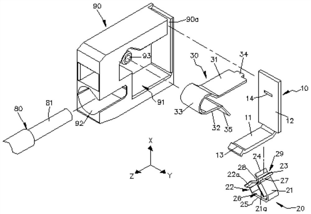
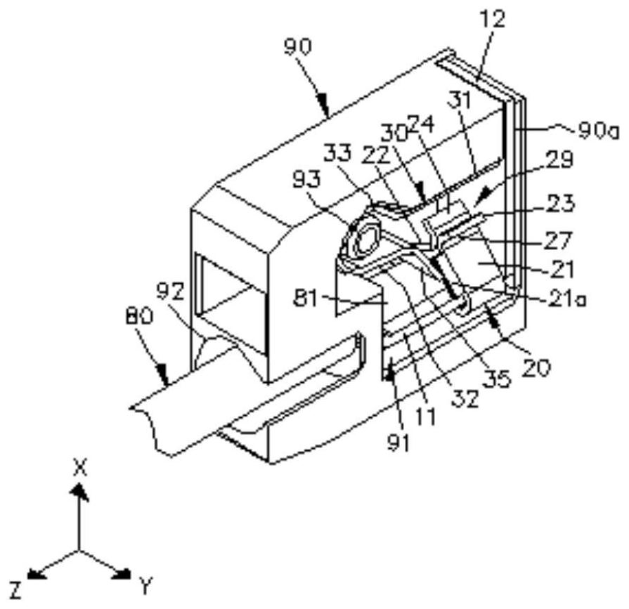
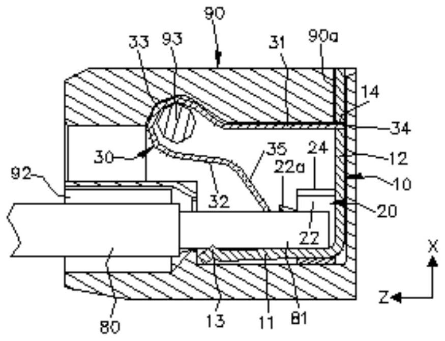
[0040] see figure 1 , figure 2 and image 3 , figure 1 It is an exploded perspective view of the three-dimensional structure of the conductive component according to an embodiment of the present invention; it shows the structural situation of the shell, the main body of the conductive component, the metal shrapnel, and the limiting body. figure 2 It is a schematic diagram of the three-dimensional structure combination of the present invention. image 3 for figure 2 A schematic diagram of a planar structure; showing the structural coordination of the body, metal shrapnel, limiting body and wires. Such as figure 1 , figure 2 and image 3As shown, the conductive assembly structure of the wire connection device of the present invention includes a combination of a body 10 and a limiting body 20 . The conductive component (or body 10, limiting body 20) is defined with X-direction reference axis, Y-direction reference axis and Z-direction reference axis which are perpendi...


PUM


Abstract

The invention relates to a conductive component structure of a wire connecting device, which provides functions such as increasing the conductive performance and the stability of the combined wire. The conductive assembly includes a plate-shaped body and a limiting body connected to the body; and, the limiting body has a base, a first arm connected to the base, a second arm and a free section connected to the first arm and the second arm, and the common The restricting body has an elastic clamping effect. When the wire is inserted into the contact conductive component, the end of the wire is at least pressed between the first arm and the second arm of the restricting body to form a fixation; to improve the wire is easy to shift or shake due to external force, and the contact is not stable, which affects the conduction efficiency and safety, etc.

Description

technical field [0001] The invention relates to a conductive assembly structure of a wire connection device, in particular to a technology in which the conductive assembly is provided with a limiting body for guiding and assisting in fixing the wire. Background technique [0002] In the prior art, metal components (or conductive components) and shrapnel conductors (or metal shrapnel) covered in insulating shells (usually made of plastic materials) are used to press or connect the wires entering the terminal, forming A terminal device or switch connection device that electrically connects or releases a conductor. For example, CN 102204015 A "Electrical Connecting Terminal", DE 29915515U1, EP 2325947 A1, China Taiwan No. 103206602 "Switch Terminal Block Structure", No. 104134448 "Switch Wiring Device" patent cases, etc., provide typical embodiments. [0003] The prior art also discloses a plurality of electrical connection terminals arranged in a snap-fit ​​ground track (or c...

Claims


Application Information

Patent Timeline
Patent Type & Authority Patents(China)
IPC IPC(8): H01R13/502H01R13/15H01R13/639
CPCH01R13/15H01R13/502H01R13/639
Inventor 吴智远陈玮奇戴明杉
Owner SWITCHLAB SHANGHAI
Why Eureka
Try Eureka