Intelligent electricity utilization fire detector convenient to accommodate

A technology for fire detectors and intelligent electricity utilization, which can be applied to fire alarms, instruments, alarms, etc., and can solve the problems of inconvenient storage and storage

Active Publication Date: 2019-09-24
合肥荣事达电子电器集团有限公司
View PDF4 Cites 2 Cited by
  • Summary
  • Abstract
  • Description
  • Claims
  • Application Information

AI Technical Summary

Problems solved by technology

[0003] The patent number is 201320727501.0, and the patent name is a technical solution for an openable and closable leakage fire detector, which can be easily disassembled and assembled, and has the advantages of compact structure, easy assembly, convenient use, and safe operation. The electric fire detector in the scheme is inconvenient to organize and store

Method used


Image

  • Intelligent electricity utilization fire detector convenient to accommodate
  • Intelligent electricity utilization fire detector convenient to accommodate
  • Intelligent electricity utilization fire detector convenient to accommodate

Examples


Embodiment 1

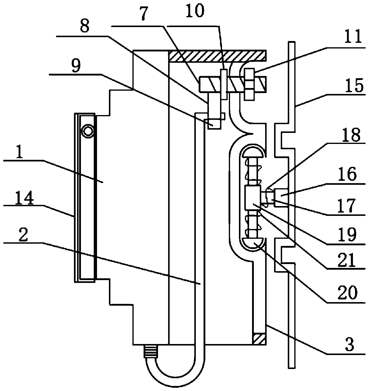
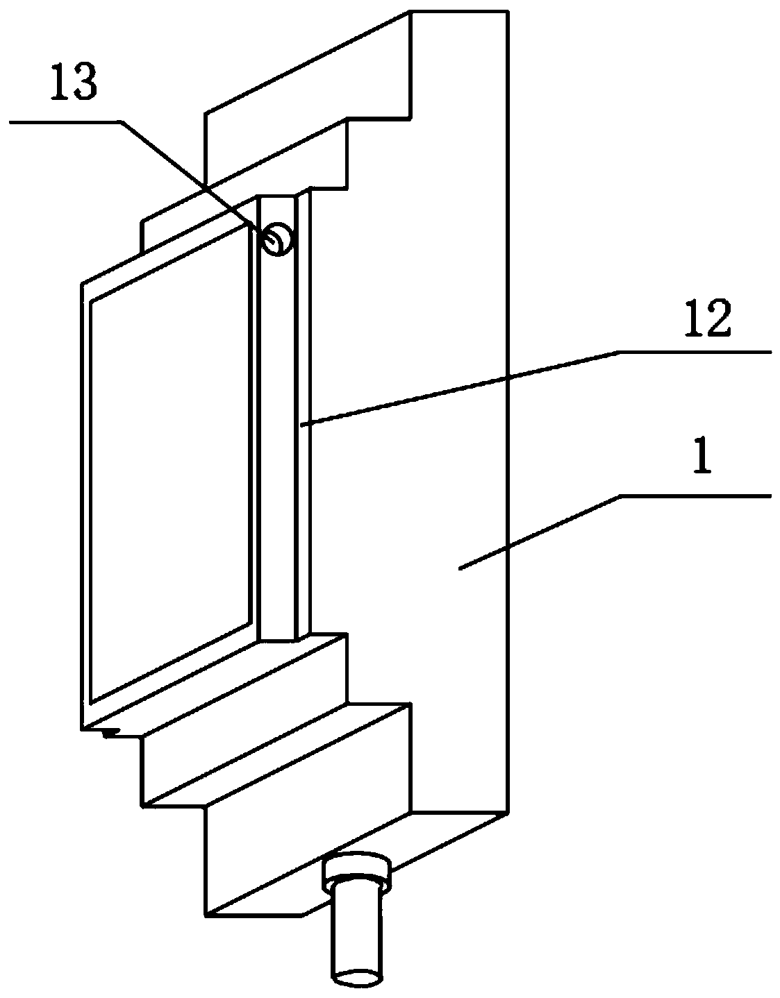
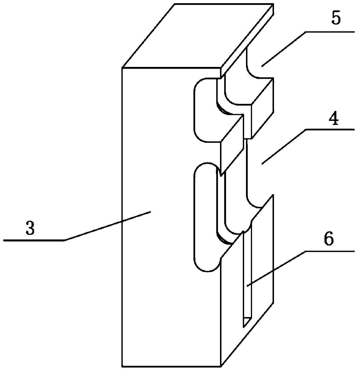
[0026] Such as Figure 1-4 As shown, an intelligent electric fire detector that is easy to store includes a detector body 1, a cable 2 is connected to the lower end of the detector body 1, a housing 3 is connected to the rear end of the detector body 1, and the lower end of the housing 3 Opening, the housing 3 is provided with a guide rail groove 4, the guide rail groove 4 protrudes toward the side of the detector body 1, and the side wall of the housing 3 away from the detector body 1 is provided with a strip-shaped hole 6, and the side wall of the strip-shaped hole 6 There is a screw 7 inserted in the interior, and a section of the screw 7 located inside the housing 3 is connected with an arc-shaped iron plate 8 and a limit ring 10. The arc-shaped iron plate 8 is located between the detector body 1 and the limit ring 10, and the limit The radius of the ring 10 is greater than the width of the strip hole 6, the arc iron plate 8 is adsorbed with a permanent magnet 9, the movab...

Embodiment 2

[0029] Such as Figure 1-5 As shown, an intelligent electric fire detector that is easy to store includes a detector body 1, a cable 2 is connected to the lower end of the detector body 1, a housing 3 is connected to the rear end of the detector body 1, and the lower end of the housing 3 Opening, the housing 3 is provided with a guide rail groove 4, the guide rail groove 4 protrudes toward the side of the detector body 1, and the side wall of the housing 3 away from the detector body 1 is provided with a strip-shaped hole 6, and the side wall of the strip-shaped hole 6 There is a screw 7 inserted in the interior, and a section of the screw 7 located inside the housing 3 is connected with an arc-shaped iron plate 8 and a limit ring 10. The arc-shaped iron plate 8 is located between the detector body 1 and the limit ring 10, and the limit The radius of the ring 10 is greater than the width of the strip hole 6, the arc iron plate 8 is adsorbed with a permanent magnet 9, the movab...


PUM


Abstract

The invention relates to the technical field of electric fire detectors, and particularly relates to an intelligent electricity utilization fire detector convenient to accommodate. The lower end of a detector body is connected with a cable, the rear end of the detector body is connected with a shell, the lower end of the shell is open, the shell is provided with a guide rail groove, the guide rail groove protrudes towards one side of the detector body, the side wall, which is away from the detector body, of the shell is provided with a strip-shaped hole, and the internal part of the strip-shaped hole is movably inserted with a screw. The free end of the cable on the detector body is put between an arc iron plate and a permanent magnet, the position of the cable is fixed, the screw is rotated to wind the cable until the cable is in a tensioned state, and the position of the screw is fixed by a nut. According to the device, the setting of the guide rail groove enables the detector body to be applicable to the guide rail type installation, and the cable is fixed inside the shell by using the combination structure of the arc iron plate and the permanent magnet, thereby facilitating the arrangement and accommodation of the detector body.

Description

technical field [0001] The invention relates to the technical field of electric fire detectors, in particular to an intelligent electric fire detector that is convenient for storage. Background technique [0002] Electric fire detector is a kind of equipment commonly used in fire protection to detect fires caused by electric leakage in lines, and reduce the risk of electrical fires through active preventive maintenance measures. [0003] The patent number is 201320727501.0, and the patent name is a technical solution for an openable and closable leakage fire detector, which can be easily disassembled and assembled, and has the advantages of compact structure, easy assembly, convenient use, and safe operation. The electrical fire detectors in the scheme are inconvenient to organize and store them. [0004] In view of the above problems, an intelligent electric fire detector that is easy to store is designed. Contents of the invention [0005] The object of the present inv...

Claims


Application Information

Patent Timeline
Patent Type & Authority Applications(China)
IPC IPC(8): H05K5/02H05K7/14G08B17/00
CPCH05K5/0204H05K5/0247H05K7/14G08B17/00H05K5/03
Inventor 姚文森凌茜蕾
Owner 合肥荣事达电子电器集团有限公司
Why Eureka
Try Eureka