A variable building skin system based on light sensing

A light-sensing and architectural technology, applied in the direction of sustainable buildings, buildings, building components, etc., can solve the problems of reflective plate installation area and reflective area limitation, complex and changeable forms, and high reflected light intensity, so as to change the quality of light environment , avoid light pollution, reduce the effect of building load

Active Publication Date: 2020-10-02
TONGJI UNIV
View PDF8 Cites 0 Cited by
  • Summary
  • Abstract
  • Description
  • Claims
  • Application Information

AI Technical Summary

Problems solved by technology

However, due to the high intensity of its reflected light, the flat reflector can only be used in the upper area of ​​a certain layer, otherwise it will cause light pollution
Moreover, modern architectural forms are complex and changeable, not simple layer upon layer
This greatly restricts the installation area and reflective area of ​​the reflector

Method used


Image

  • A variable building skin system based on light sensing
  • A variable building skin system based on light sensing
  • A variable building skin system based on light sensing

Examples


Embodiment 1

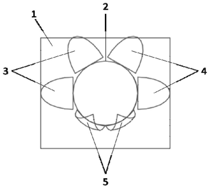
[0038] Such as figure 1 A variable building skin system based on light sensing is shown in the application such as Figure 4 and Figure 5A south-facing room is shown, installed on the south wall in close-packed form. Assume that the people in the room sit on both sides of the desk 8 . The illuminance sensor 7 is installed on both sides of the desk 8, at a position of 1.35m from the ground (i.e. the normal sitting height of a person), to prevent direct light from entering the field of view of the personnel sitting on both sides of the desk 8.

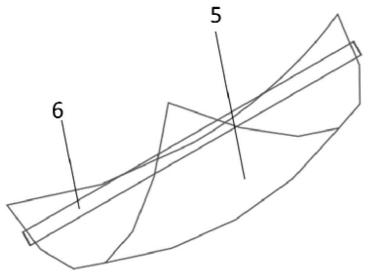
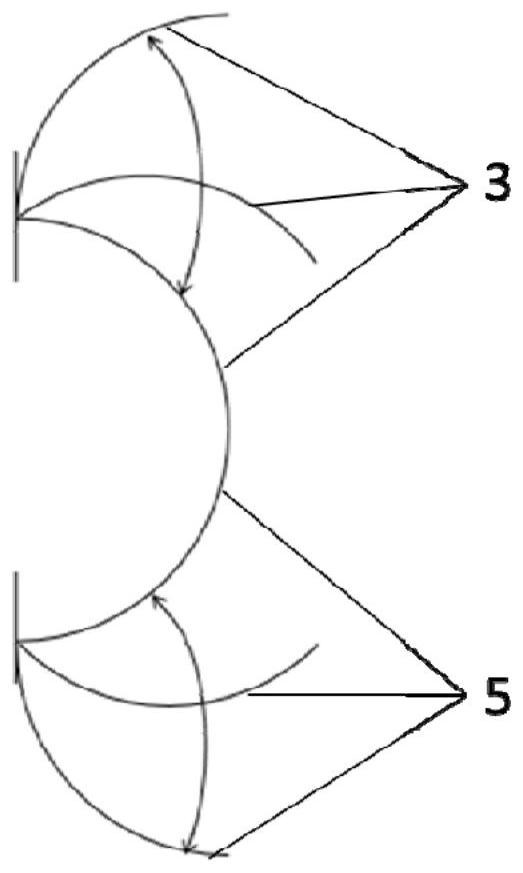
[0039] The first light-shielding component 3 , the second light-shielding component 4 and the light-reflecting unit 5 are formed by dividing a hemispherical surface into six parts by cutting a cake through its apex. Such as figure 2 The shown reflective unit 5 is driven by the turning shaft in the tangential direction of the arc at the midpoint of the bottom arc. Such as image 3 As shown, the first shading assembly 3, the second...

Embodiment 2

[0050] A variable building skin system based on light sensing, the system includes a wall 1, a circular window 2 arranged on the wall 1, and a shading unit and a reflective unit 5 respectively flipped on the wall 1. The shading unit is located at On the upper edge of the circular window 2, the reflective unit 5 is located on the lower edge of the circular window 2. The shading unit can not only block direct light, but also control the amount of light entering the room by adjusting the inclination angle of the shading unit. The reflective unit 5 is used to increase the amount of light entering the room. Adjust the inclination angle of the shading unit and reflective unit 5 as needed to increase indoor natural lighting . The light sensing unit is arranged in different areas of the room according to the needs, monitors the lighting effect of the area, provides real-time feedback, and adjusts the inclination angle of the shading unit and the reflective unit 5 located at different ...


PUM


Abstract

The invention relates to a variable building skin system based on light induction. The system includes a wall, a circular window arranged on the wall, and a shading unit and a reflective unit respectively flipped and arranged on the wall. The shading unit is located in a circular window. On the upper edge of the window, the reflective unit is located on the lower edge of the circular window, and the system also includes a light sensing unit. Compared with the prior art, the present invention uses sensor technology and unique skin structure to instantly control the amount and direction of natural light entering the room, thereby changing the quality of the indoor light environment and indoor comfort; the present invention has a wide shading range and can block direct sunlight from all directions Light, in particular, can avoid the sun in the east and the west; the present invention can selectively shade indoor activities, and introduce natural light as much as possible to reduce the lighting load; the present invention introduces natural light in the form of concave reflection to avoid light pollution caused by too strong reflected illumination; the present invention Equipped with illuminance sensor and rain sensor to monitor weather changes, and feed back to the controller for immediate response.

Description

technical field [0001] The invention belongs to the technical field of shading building equipment, and relates to a variable building skin system based on light induction. Background technique [0002] At present, the most commonly used automatic sun-shading methods for buildings are shutters of various colors, but these shutters in the horizontal direction can only effectively shade the sun without affecting the field of vision when the sun’s altitude angle is relatively large. When the sun altitude angle is small in the morning or afternoon, there will be a contradiction between vision and shading: to achieve effective shading, the blinds will seriously block the vision, and the indoors cannot see the outdoors, which is no different from ordinary blackout curtains, which is not conducive to indoor lighting; If the vision is not affected, the sunlight will enter the room through the louver gap, which will easily cause glare. At these times, the sun's altitude angle is smal...

Claims


Application Information

Patent Timeline
Patent Type & Authority Patents(China)
IPC IPC(8): E06B9/24E06B7/26E04F10/10G02B7/182
CPCE06B9/24E06B7/26E04F10/10G02B7/1821E06B2009/2417E06B2009/2482Y02A30/24Y02B80/00
Inventor 史洁张书良周雨彤冉博文宋德萱曹祥
Owner TONGJI UNIV
Why Eureka
Try Eureka