
Method and device for monitoring IO time delay of distributed file system and storage medium

A distributed file and delay technology, applied in file system, file system function, digital data information retrieval and other directions, can solve the problems of large amount of data, unreasonable, indistinguishable io size, etc., to achieve rapid pressure and ensure accuracy. Effect

Active Publication Date: 2019-09-27
PING AN TECH (SHENZHEN) CO LTD
View PDF7 Cites 3 Cited by
  • Summary
  • Abstract
  • Description
  • Claims
  • Application Information

AI Technical Summary

Problems solved by technology

[0004] First of all, if you want to monitor the delay of io, you must record the time consumed by each io. However, in actual business, the size of io is always uncertain, and io of different sizes are generated in the system every moment. It is unrealistic to record the time delay of each io of different sizes, because the amount of data recorded in this way will be too large, which is not applicable in actual production
[0005] Secondly, the io delay statistics of the existing distributed file system (ceph) is to obtain the average io delay by dividing the total accumulated io time by the number of io, and does not distinguish the size of io; for example, an io with a size of 4kB Latency and a 4mB io delay, using a general accumulation and averaging method cannot intuitively reflect the io delay of the current system. A 4kB io consumes 2ms, and a 4mB io consumes 100ms. If Using the method of the prior art to calculate, the average delay is 2+100 / 2=51ms, if 51ms is used to judge the io delay of 4kB and 4MB, 51ms is extremely unreasonable for 4kB io, and 51ms is for 4mB of io may be reasonable again
[0006] To sum up, the method of obtaining the average io delay in the prior art cannot provide an effective basis for analyzing and monitoring the io delay of the current system

Method used


Image

  • Method and device for monitoring IO time delay of distributed file system and storage medium
  • Method and device for monitoring IO time delay of distributed file system and storage medium
  • Method and device for monitoring IO time delay of distributed file system and storage medium

Examples


Embodiment Construction

[0034] In the following description, for purposes of explanation, numerous specific details are set forth in order to provide a thorough understanding of one or more embodiments. It may be evident, however, that these embodiments may be practiced without these specific details. In other instances, well-known structures and devices are shown in block diagram form in order to facilitate describing one or more embodiments.

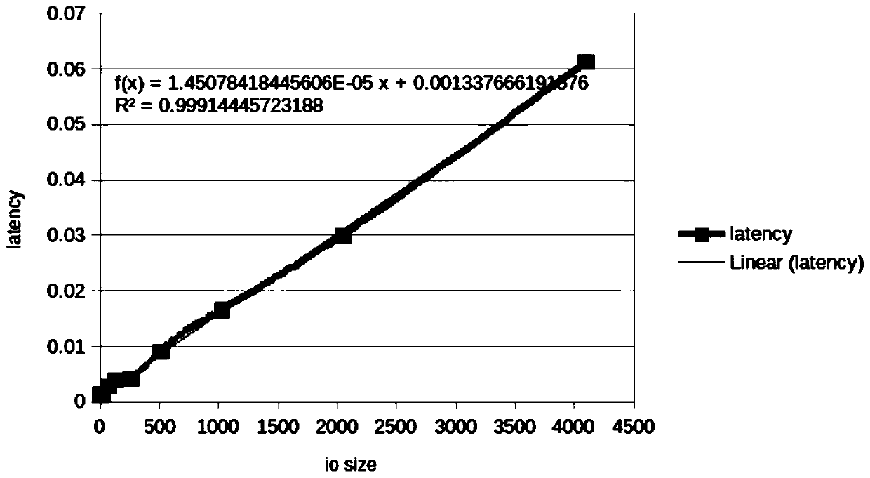
[0035] The invention provides a method for monitoring IO time delay of a distributed file system, an electronic device and a storage medium. The present invention at first obtains the linear equation of calculating the theoretical value of io time delay according to the existing experience value, thereby calculates the theoretical time delay value of any io according to the linear equation; secondly, divides the io into sections and counts the time delay between sections; S is the interval unit, and the io in each interval unit is approximately the same dela...


PUM


Abstract

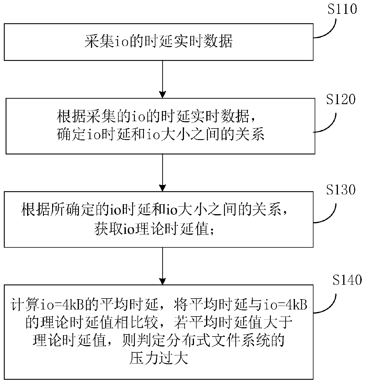
The invention provides a method and device for monitoring IO time delay of a distributed file system and a storage medium, and relates to the distributed file system in the technical field of cloud storage, and the method comprises the following steps: S110, collecting io time delay real-time data; s120, obtaining the relation between the io time delay and the io size according to the collected io time delay real-time data; s130, obtaining an io theoretical time delay value according to the determined relationship between the io time delay and the io size; s140, calculating an average time delay value of io = 4kB; and comparing the average time delay value with a theoretical time delay value of io = 4kB, and if the average time delay value is greater than the theoretical time delay value, judging that the pressure of the distributed file system is too high. By utilizing the method, the data volume can be reduced on the premise of ensuring the time delay statistical precision, and an effective basis is provided for analyzing and monitoring the io of the current system.

Description

technical field [0001] The present invention relates to a distributed file system in the technical field of cloud storage, and more specifically, to a method for monitoring IO (Input / Output) delay of a distributed file system, an electronic device and a storage medium. Background technique [0002] In this era of information explosion, it is no longer sufficient to simply expand the storage capacity of computer file systems through hard disks. The emergence of cloud storage distributed file systems provides the possibility to solve storage problems; to improve data io through parallel access performance (I / O input / output Input / Output), the distributed file system stores data in strips on different disks of each data server. However, if the business pressure of the disk is too high, the IO performance of the distributed file system will be significantly reduced. It is a common practice to judge the business pressure of the disk by the IO delay. In a distributed file system, ...

Claims


Application Information

Patent Timeline
IPC IPC(8): G06F16/17G06F16/182
CPCG06F16/1734G06F16/182Y02D10/00
Inventor 卢洪棚
Owner PING AN TECH (SHENZHEN) CO LTD
Learn More