Automatic analysis device and cleaning mechanism in automatic analysis device

A technology of automatic analysis device and cleaning mechanism, which is applied in the direction of analyzing materials, cleaning hollow objects, and containers used in laboratories, etc., and can solve problems affecting analysis results, etc.

Active Publication Date: 2019-09-27
HITACHI HIGH-TECH CORP
View PDF4 Cites 1 Cited by
  • Summary
  • Abstract
  • Description
  • Claims
  • Application Information

AI Technical Summary

Problems solved by technology

At this time, if there is residual liquid in the cleaned reaction vessel, it will affect the subsequent analysis results

Method used


Image

  • Automatic analysis device and cleaning mechanism in automatic analysis device
  • Automatic analysis device and cleaning mechanism in automatic analysis device
  • Automatic analysis device and cleaning mechanism in automatic analysis device

Examples


Embodiment 1

[0033]

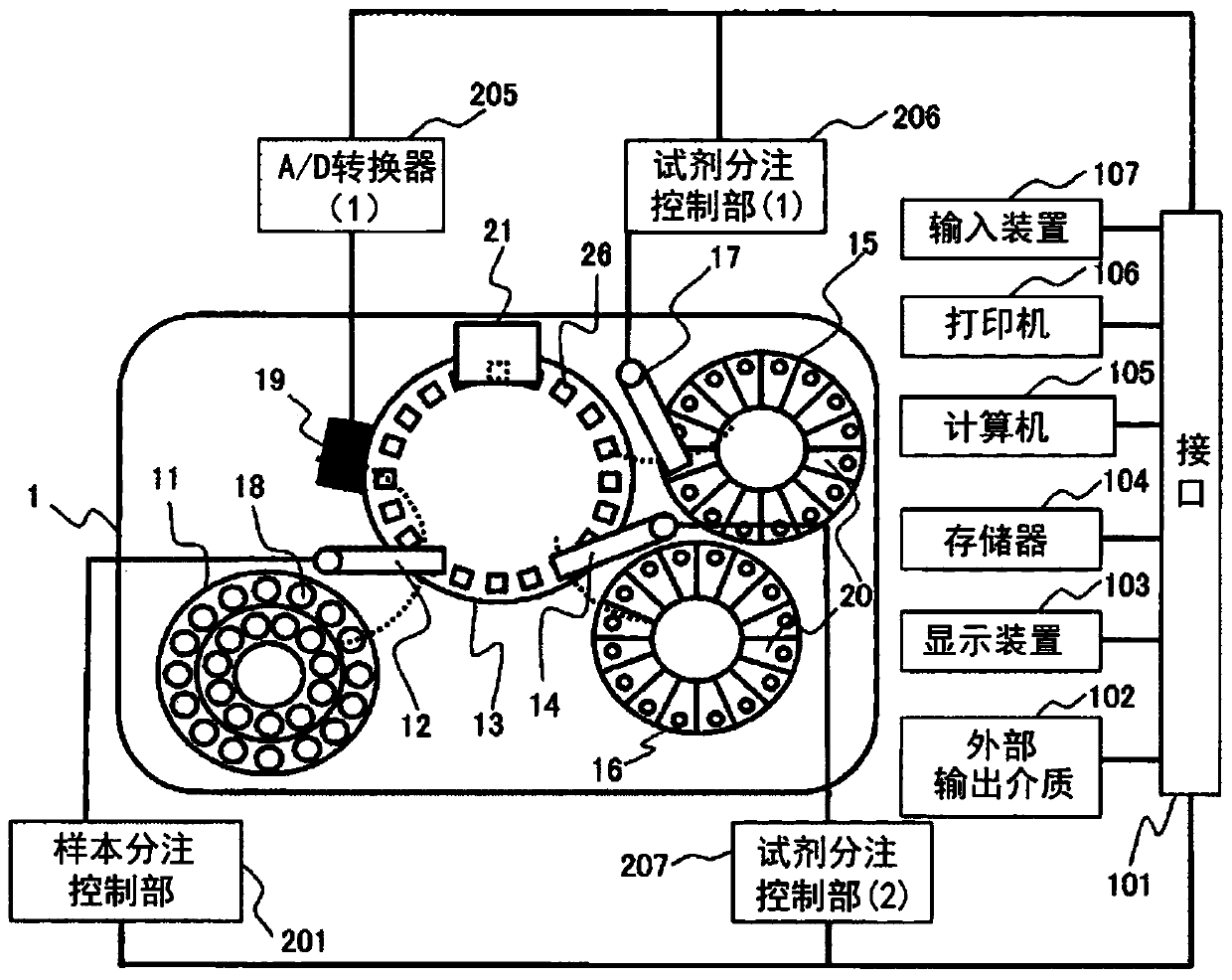
[0034] figure 1 It is a figure which shows the basic structure of the automatic analysis apparatus concerning this embodiment. Here, as one mode of the automatic analysis device, an example of a turntable system biochemical analysis device will be described.

[0035] As shown in this figure, the housing of the automatic analyzer 1 is equipped with a reaction disk 13, a sample disk 11, a first reagent disk 15, a second reagent disk 16, a photometer 19, and a cleaning mechanism 21.

[0036] The reaction disk 13 is a disk-shaped unit that can freely rotate clockwise and counterclockwise, and a plurality of reaction vessels 26 can be arranged on the circumference of the reaction disk 13.

[0037] The sample tray 11 is a disk-shaped unit that can freely rotate clockwise and counterclockwise, and a plurality of sample containers 18 for storing biological samples such as standard samples or test samples can be arranged on the circumference of the sample tray 11.

[0038] The first r...

Embodiment 2

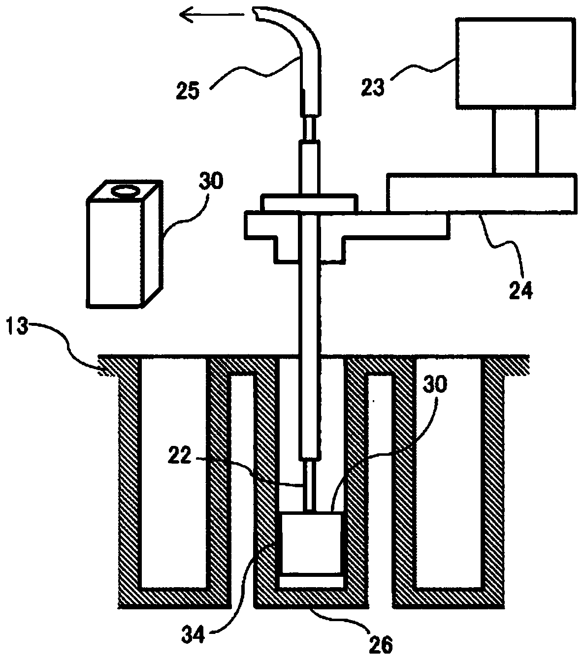
[0077] Next, another configuration of the cleaning mechanism 21 of the automatic analyzer 1 according to this embodiment will be described. In the above-mentioned Example 1, a case where the height of the cleaning head 30 is lower than the height of the reaction vessel 26 (the height from the opening (upper end) to the bottom surface (lower end)) is illustrated and described. Here, use Image 6 A structure in which the height of the cleaning head 30 is set to be approximately the same as the height from the opening to the bottom surface of the reaction vessel 26, and the cone 31a is provided from the upper end to the lower end of the cleaning head 30 will be described. Image 6 It is a figure which shows the structure of the cleaning mechanism provided with the cleaning head which concerns on this embodiment (Example 2). In addition, in this figure, and Figure 4 Same, shown from relative to figure 2 It is a view viewed from an angle such that the right side of the reaction dis...

Embodiment 3

[0081] Next, another configuration of the reaction vessel 26 of the automatic analyzer 1 according to the present embodiment will be described. In the above-mentioned embodiment, the structure of the reaction vessel 26 using a rectangular parallelepiped composed of rectangles on all surfaces has been described. Figure 7 A case where the following reaction vessel (hereinafter referred to as the tapered reaction vessel 33) is used will be described. The reaction vessel is formed as a part of the reaction vessel, that is, when the lower end of the cleaning head 30 is in contact with the bottom surface, the cleaning head In the rectangular parallelepiped region 33a (first region) from the position of the upper end of 30 to the bottom surface of the reaction vessel, the cross-sectional area of ​​the surface perpendicular to the direction in which the cleaning head 30 is inserted into the reaction vessel is equal; from the upper end of the cleaning head 30 to the reaction vessel In t...


PUM


Abstract

There is a possibility that, due to contact by a cleaning tip for sucking up a cleaning liquid for the next analysis when the inside of a repeatedly used reaction container is cleaned, the inner wall of the reaction container was damaged and thereby an analysis result was affected. The invention provides a device and a cleaning mechanism for a reaction container in the device that are characterized by being provided with: a reaction disk for holding a reaction container; a sample dispensing mechanism for dispensing a sample to the reaction container; a reagent dispensing mechanism for dispensing a reagent to the reaction container; an optical system comprising a light source for applying light to a mixture of the sample and the reagent dispensed to the reaction container, and a detector for detecting the light applied from the light source; and a cleaning mechanism for cleaning the reaction container, wherein the cleaning mechanism is provided with a cleaning liquid supply nozzle for supplying a cleaning liquid to the reaction container after an analysis, a cleaning liquid suction nozzle for suctioning the supplied cleaning liquid, and a cleaning tip provided on the lower end of the cleaning liquid suction nozzle, and the side surface of the cleaning tip is formed such that the width of the cleaning tip becomes smaller downward, in the state where the cleaning tip is inserted into the reaction container, in at least a surface opposing the light source and a surface opposing the detector, and in a range that overlaps with a photometric range in which light applied to the reaction container from the light source passes through the reaction container toward the detector or in a range that is larger than the photometric range.

Description

Technical field [0001] The present invention relates to an automatic analysis device for analyzing biological samples such as blood and urine, and more particularly to a cleaning mechanism for cleaning a reaction container and an automatic analysis device equipped with the cleaning mechanism. Background technique [0002] The automatic analyzer is a device that qualitatively and quantitatively analyzes biological samples (hereinafter, sometimes referred to as samples or samples) such as blood and urine. The sample and the reagent are reacted in the reaction container, and the measurement target component in the sample is analyzed. The reaction vessel is made of materials such as plastic or glass. Especially in a device that analyzes items such as biochemical analysis, the reaction vessel that has been measured once is generally washed and reused. The cleaning operation of the reaction vessel is to move the reaction vessel to a predetermined cleaning position, repeatedly inject a...

Claims


Application Information

Patent Timeline
Patent Type & Authority Applications(China)
IPC IPC(8): G01N35/02
CPCG01N2035/0437G01N2035/0444G01N35/04G01N35/1002B01L13/02B01L2200/141B01L2200/16B01L2300/0609B01L2300/0663B01L2300/0803B01L3/5085B01L3/502B08B9/087B08B9/093B08B2209/08
Inventor 盐谷圭饭岛昌彦
Owner HITACHI HIGH-TECH CORP
Why Eureka
Try Eureka