
Fuel-cell electric vehicle

a fuel cell and electric vehicle technology, applied in battery/fuel cell control arrangement, electrochemical generators, transportation and packaging, etc., can solve the problems of increasing the size of the power source, increasing the volume flow rate of the reactant gas as well as the flow velocity, and increasing the amount of residual water removed from inside the fuel cell. , to achieve the effect of increasing the volume flow rate of the reactant gas and the flow velocity, increasing the efficiency of electric power generation, and reducing the amount of residual water

Inactive Publication Date: 2016-01-26
HONDA MOTOR CO LTD
View PDF9 Cites 0 Cited by
  • Summary
  • Abstract
  • Description
  • Claims
  • Application Information

AI Technical Summary

Benefits of technology

The patent text describes a method of reducing water in a fuel cell of an electric vehicle before it is stopped. By predicting when the vehicle will stop and reducing water in the fuel cell, it helps to scavenge the water more quickly, reducing energy consumption and noise. This results in a more efficient and comfortable vehicle operation.

Problems solved by technology

When the fuel cell is used under low-temperature conditions, product water remaining inside the fuel cell (residual water) would become frozen, which would deteriorate a membrane electrode assembly or MEA and lower its startup characteristics, thus significantly impairing its marketability for these or other reasons.
However, typical scavenging processes used in a fuel cell system require a large amount of energy, for which electric power should be fed from a power source other than the fuel cell, such as a battery, thus increasing the size of the power source.
In addition, such scavenging processes would produce noises.
Consequently, the scavenging processes could disadvantageously impair the marketability.

Method used


Image

  • Fuel-cell electric vehicle
  • Fuel-cell electric vehicle
  • Fuel-cell electric vehicle

Examples


Embodiment Construction

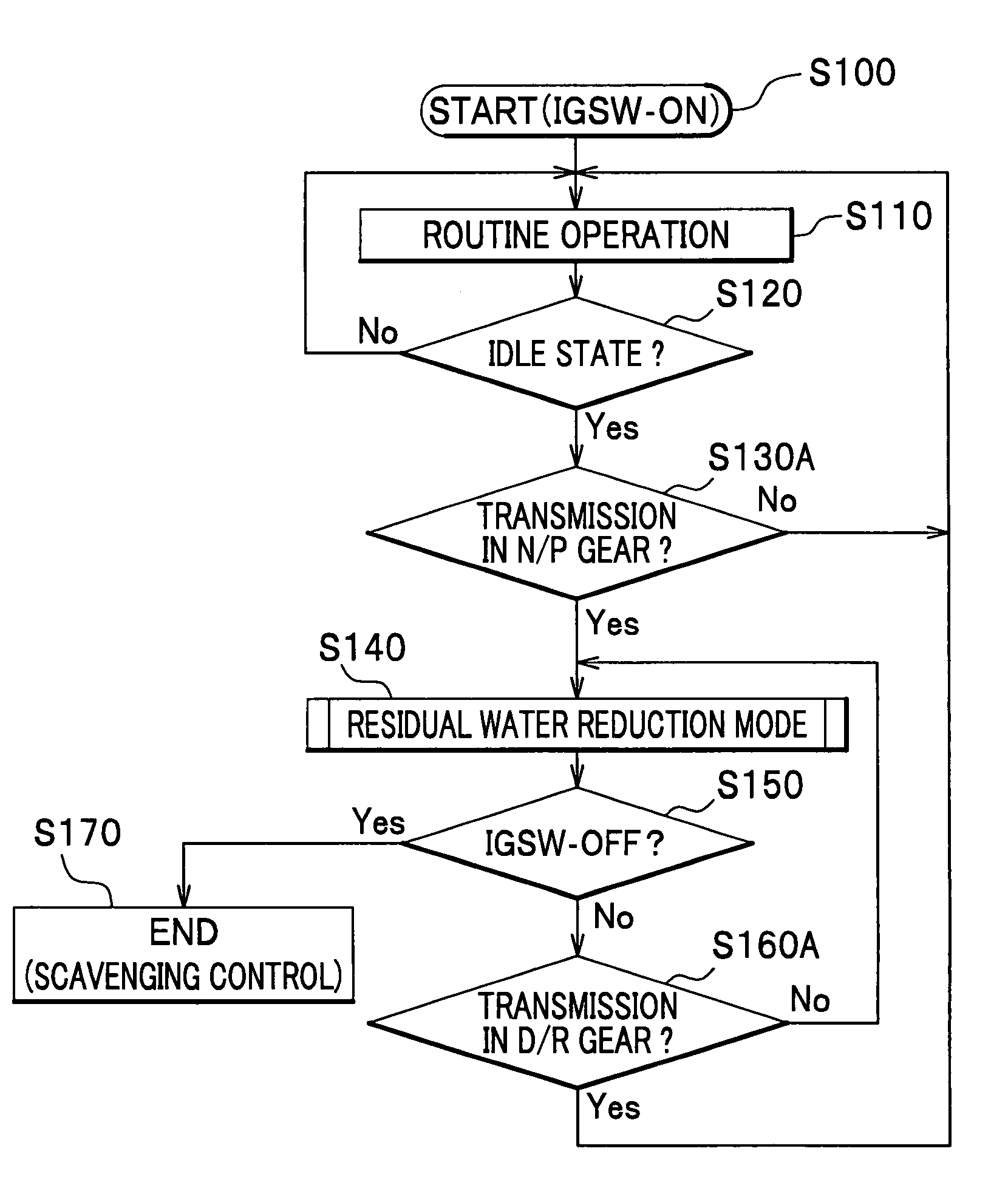
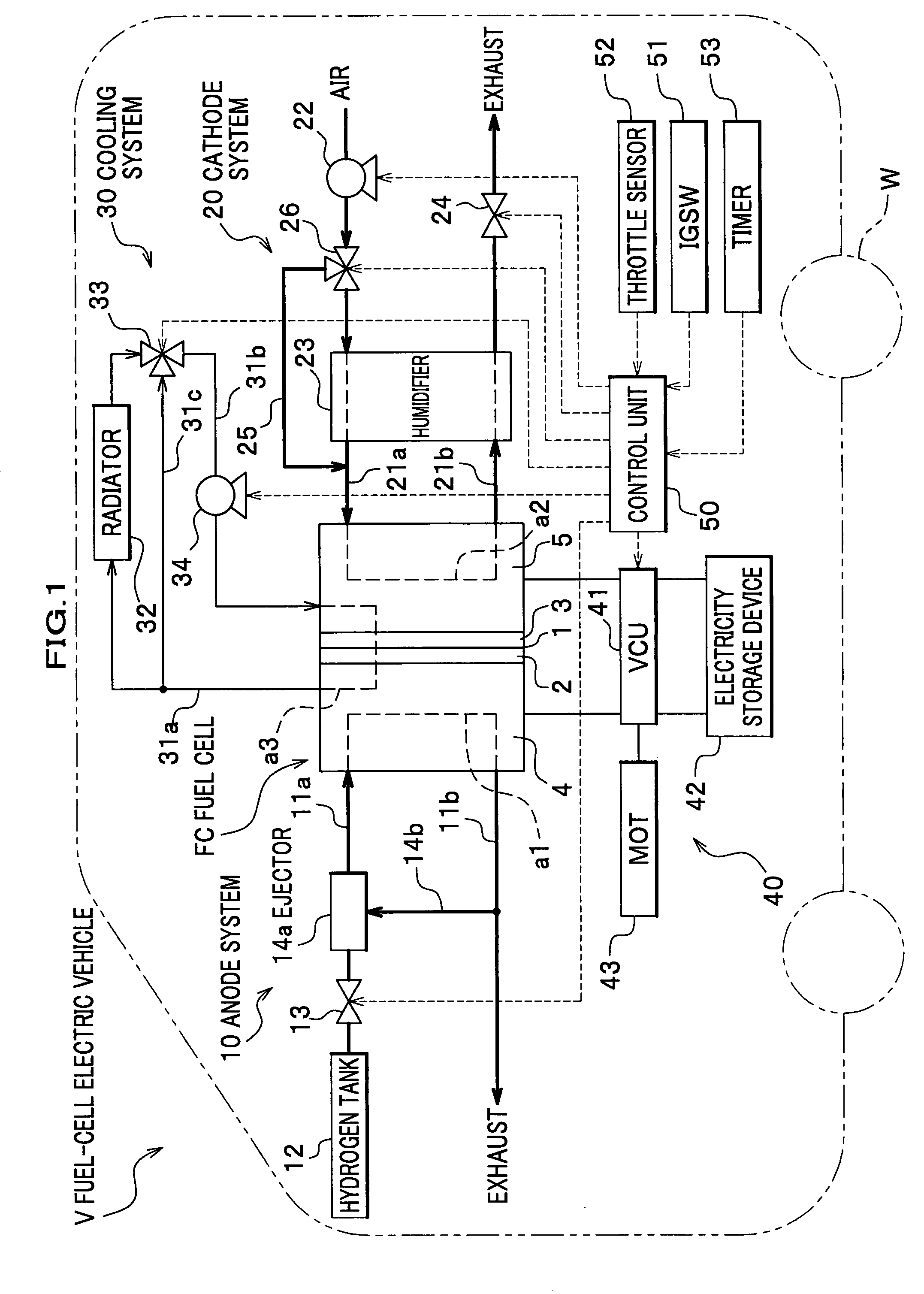
[0027]As shown in FIG. 1, a fuel-cell electric vehicle V according to one exemplary embodiment of the present invention includes a fuel cell FC, an anode system 10, a cathode system 20, a cooling system 30, a high-voltage system 40, a control unit 50, and various other components.

[0028]The fuel cell FC is provided as a fuel cell stack consisting of unit cells. Each unit cell is comprised of a solid polymer electrolyte membrane (hereinafter referred to simply as “electrolyte membrane”) 1, an anode 2, a cathode 3 and two separators 4, 5. The electrolyte membrane 1 has proton conductivity. The anode 2 is provided at one side of the electrolyte membrane 1 and the cathode 3 is provided at the other side of the electrolyte membrane 1; the electrolyte membrane 1 thus sandwiched between the anode 2 and the cathode 3 forms a membrane electrode assembly (MEA). On both sides of the MEA are provided the separators 4, 5, which not only serve to separate unit cells but also serve as manifolds to ...


PUM

PropertyMeasurementUnit
humidityaaaaaaaaaa
flow rateaaaaaaaaaa
pressureaaaaaaaaaa

Abstract

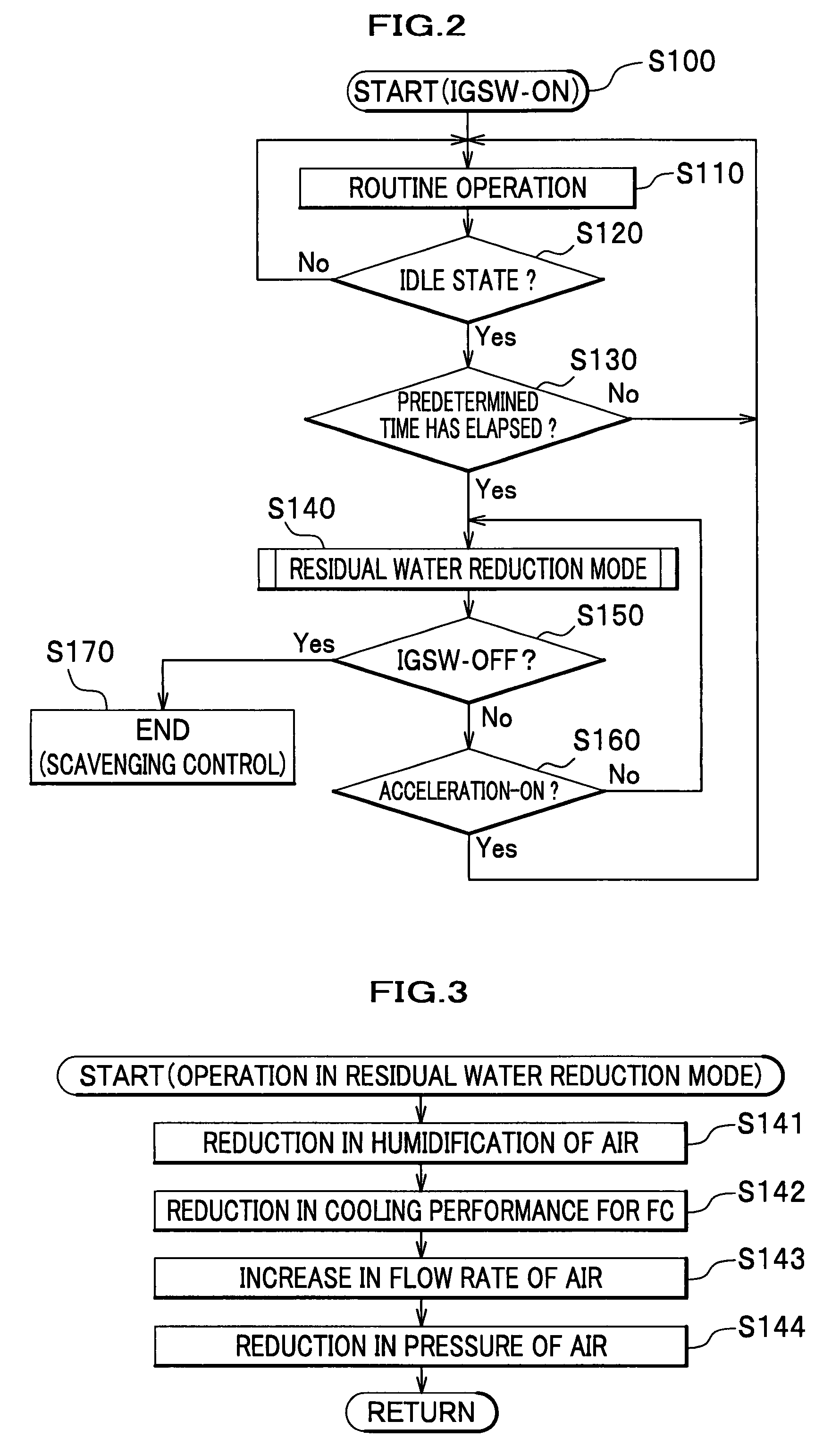
When a fuel-cell electric vehicle is running at idle, and a predetermined period of time has elapsed since the vehicle comes into the idle state, forthcoming stopping of an operation of the vehicle is predicted, and the operation mode of a fuel cell is shifted to a residual water reduction mode in which residual water remaining inside the fuel cell is reduced. In the residual water reduction mode, for example, the amount of humidification for air to be supplied to the fuel cell is reduced, so that the air with reduced humidity passes through the fuel cell, to thereby increase the amount of residual water removed by the air. Accordingly, the residual water inside the fuel cell can be reduced before the actual stopping of the operation of the vehicle.

Description

CROSS-REFERENCE TO RELATED APPLICATION(S)[0001]This application claims the foreign priority benefit under Title 35, United States Code, §119 (a)-(d), of Japanese Patent Application No. 2006-096898, filed on Mar. 31, 2006 in the Japan Patent Office, the disclosure of which is herein incorporated by reference in its entirety.BACKGROUND OF THE INVENTION[0002]This invention relates to a fuel-cell electric vehicle in which stopping of the operation of the vehicle is predicted to reduce residual water before the stopping in actuality.[0003]The fuel cell generates electricity by electrochemical reaction between hydrogen and oxygen, and produces water at the same time. When the fuel cell is used under low-temperature conditions, product water remaining inside the fuel cell (residual water) would become frozen, which would deteriorate a membrane electrode assembly or MEA and lower its startup characteristics, thus significantly impairing its marketability for these or other reasons. Accordin...

Claims


Application Information

Patent Timeline
Patent Type & Authority Patents(United States)
IPC IPC(8): H01M8/04B60L11/18
CPCB60L11/1887B60L11/1892H01M8/0491H01M8/0494H01M8/04126H01M8/04313H01M8/04731H01M8/04753H01M8/04761H01M8/04768H01M8/04835Y02T90/34B60L2260/54B60L2260/56H01M8/04156H01M8/04253H01M2250/20Y02E60/50Y02T10/92Y02T90/32B60L58/40B60L58/33Y02T90/40Y02T10/70
Inventor YOSHIDA, HIROMICHIHIBINO, KIYOHIDEJINBA, RYOYAMAZAKI, KAORU
Owner HONDA MOTOR CO LTD
Learn More