Strong draining pump structure and cleaning machine provided with strong draining pump structure

A drainage chamber and drainage pipe technology, which is applied in the direction of liquid cleaning methods, pumps, pump control, etc., can solve the problems of residual water odor, water residue, box corrosion, etc., to reduce residual water, improve service life, The effect of improving the accuracy of pressure perception

Active Publication Date: 2019-10-18
NINGBO FOTILE KITCHEN WARE CO LTD
View PDF5 Cites 0 Cited by
  • Summary
  • Abstract
  • Description
  • Claims
  • Application Information

AI Technical Summary

Problems solved by technology

However, the pressure switches currently on the market use the level of the liquid level to realize the opening and closing of the pump, which is not well combined with the structure of the pump itself, resulting in a large amount of water remaining in the pump body after the pump stops working.
[0003] For sewage lifting pumps, a large amount of residual water will not only produce peculiar smell, but also cause certain corrosion to the tank, affecting the user experience of consumers and the service life of the pump

Method used


Image

  • Strong draining pump structure and cleaning machine provided with strong draining pump structure
  • Strong draining pump structure and cleaning machine provided with strong draining pump structure
  • Strong draining pump structure and cleaning machine provided with strong draining pump structure

Examples


Embodiment 1

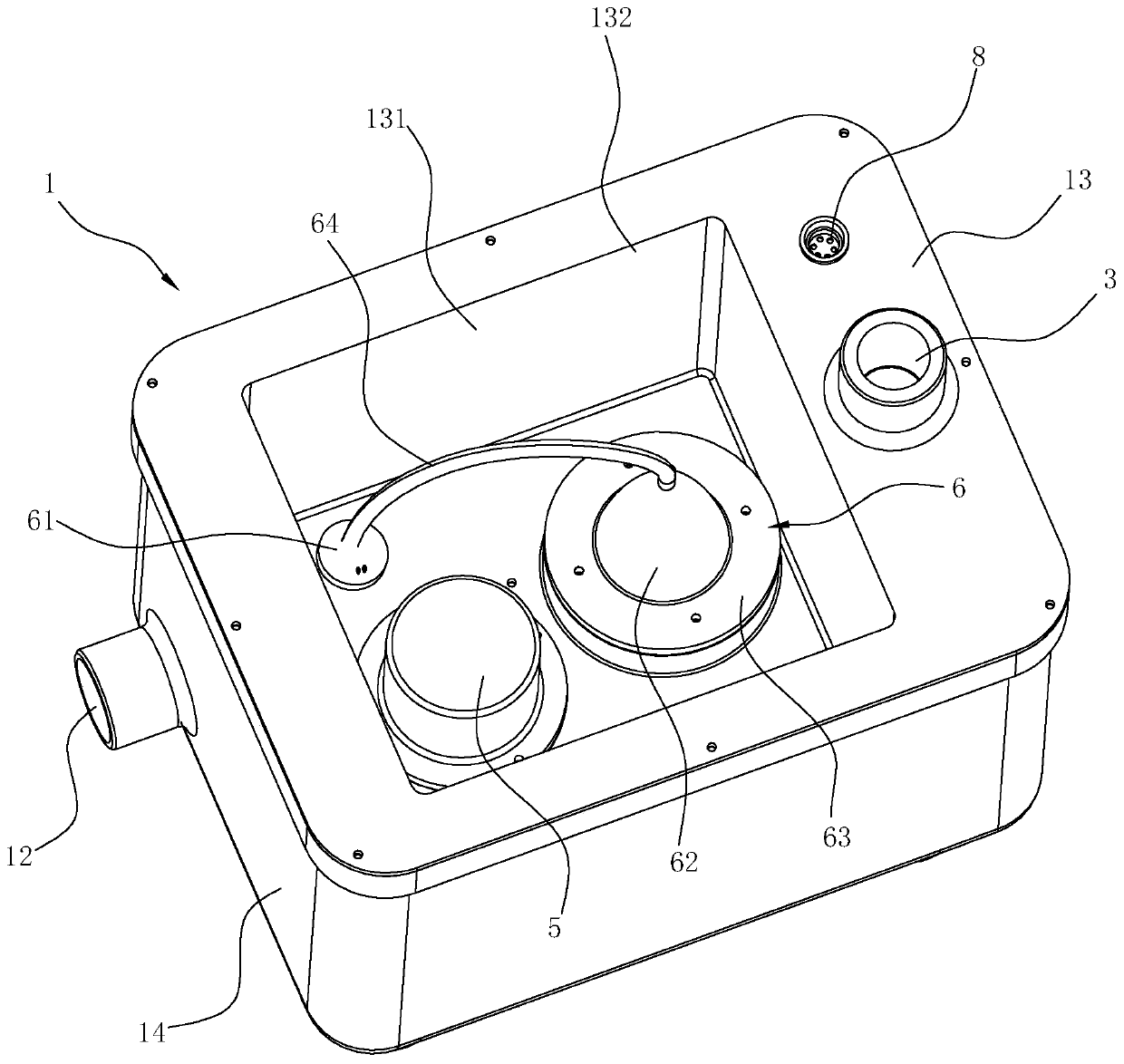
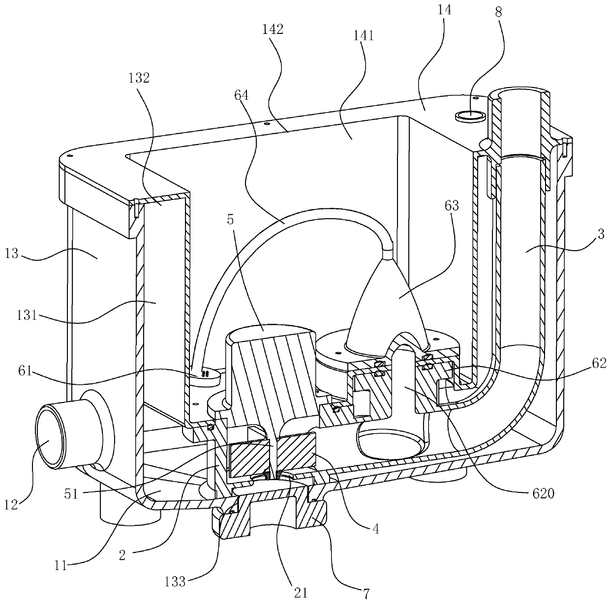
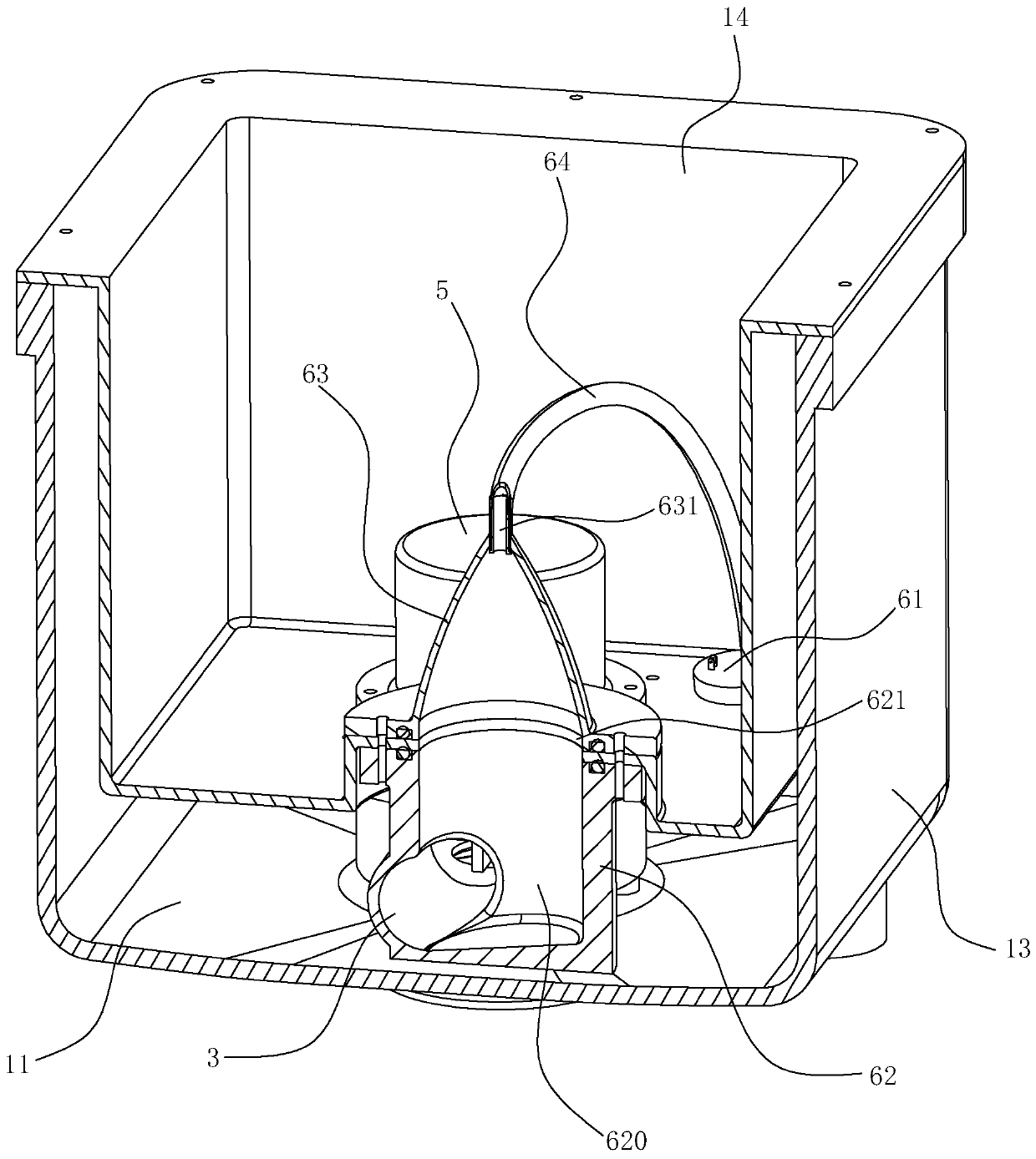
[0033] Such as Figure 1~4 As shown, the strong discharge pump junction of this embodiment includes a body 1, a volute 2, a drain pipe 3, an impeller 4, a driving member 5, and a pressure assembly 6. The interior of the body 1 is hollow to form a drainage chamber 11 with a U-shaped cross section. A first water inlet 12 for supplying water into the drain cavity 11 is opened on the side wall of 1 . The volute 2 is arranged in the drain chamber 11 , and the bottom of the volute 2 is provided with a second water inlet 21 communicating with the drain chamber 11 , and the second water inlet 21 is arranged close to the inner bottom wall of the drain chamber 11 . The drain pipe 3 is arranged in the drain cavity 11 , the first end of the drain pipe 3 communicates with the volute 2 , and the second end of the drain pipe 3 extends out of the body 1 . The impeller 4 is a centrifugal impeller, and the impeller 4 is rotatably arranged in the volute 2 and used for pumping out the water in t...

Embodiment 2

[0041] The difference between this embodiment and Embodiment 1 is that the connection position and connection method of the pressure component 6' and the volute 2' are different.

[0042] Such as Figure 5 As shown, specifically, the bottom of the housing 62' in this embodiment is connected with an air channel 65' that can communicate the pressure chamber 620' with the volute 2', and the first end of the air channel 65' is connected to the pressure chamber 620' The bottom of the air passage 65' communicates with the side of the volute 2', and the air passage 65' gradually extends downward from the first end to the second end. This structure is beneficial to prevent a large amount of water from entering the pressure chamber 620' and then pouring into the air pipe 64'.


PUM


Abstract

The invention relates to a strong draining pump structure and a cleaning machine provided with the strong draining pump structure. The strong draining pump structure comprises a body, a volute, a drain pipe, an impeller, a driving piece and a pressure assembly. The volute is directly connected with a pressure switch, in the using process, after water enters the volute from a first water inlet anda second water inlet, even if a pressure balance zone which is relatively independent is formed by the volute and the pressure assembly, with the increase of water level in the volute, the pressure inthe pressure balance zone is increased, when the pressure reaches the starting pressure of the pressure switch, the driving piece starts to drive the impeller to drain water, when the water is aboutto completely drained, due to rotation of the impeller in the volute, the internal pressure is high till the water is completely drained, the impeller rotates in an idle mode, the pressure is decreased to the stopping pressure of the pressure switch, and the driving piece drives the impeller to stop working. According to the structure, by balancing the set pressure in the volute and the pressure switch, the pressure sensing precision is improved, the amount of residual water in the pump is decreased, and the service life of the pump is prolonged.

Description

technical field [0001] The invention relates to the field of fluid power conveying structures, in particular to a strong discharge pump structure and a washing machine using the strong discharge pump structure. Background technique [0002] Existing forced discharge pumps, small household water pumps similar to sewage lift pumps, usually utilize a water level switch (pressure switch) to control the opening and closing of the pump. However, the pressure switches currently on the market use the level of the liquid level to realize the opening and closing of the pump, which is not well combined with the structure of the pump itself, resulting in a large amount of water remaining in the pump body after the pump stops working. [0003] For sewage lifting pumps, a large amount of residual water will not only produce peculiar smell, but also cause certain corrosion to the tank, affecting the user experience of consumers and the service life of the pump. [0004] Therefore, for the...

Claims


Application Information

Patent Timeline
Patent Type & Authority Applications(China)
IPC IPC(8): F04D1/00F04D15/00B08B3/02
CPCB08B3/02F04D1/00F04D15/00
Inventor 魏本柱郑峰
Owner NINGBO FOTILE KITCHEN WARE CO LTD
Why Eureka
Try Eureka