High-pressure oil pipe with composite structure
A high-pressure oil pipe and composite technology, applied in the direction of engine components, machines/engines, charging systems, etc., can solve the problems of simple structure of high-pressure oil pipe, mechanical vibration, loose joints, etc., to achieve heat preservation effect, reduce vibration amplitude, The effect of convenient production and processing
- Summary
- Abstract
- Description
- Claims
- Application Information
AI Technical Summary
Problems solved by technology
Method used
Image

Examples
Embodiment 1
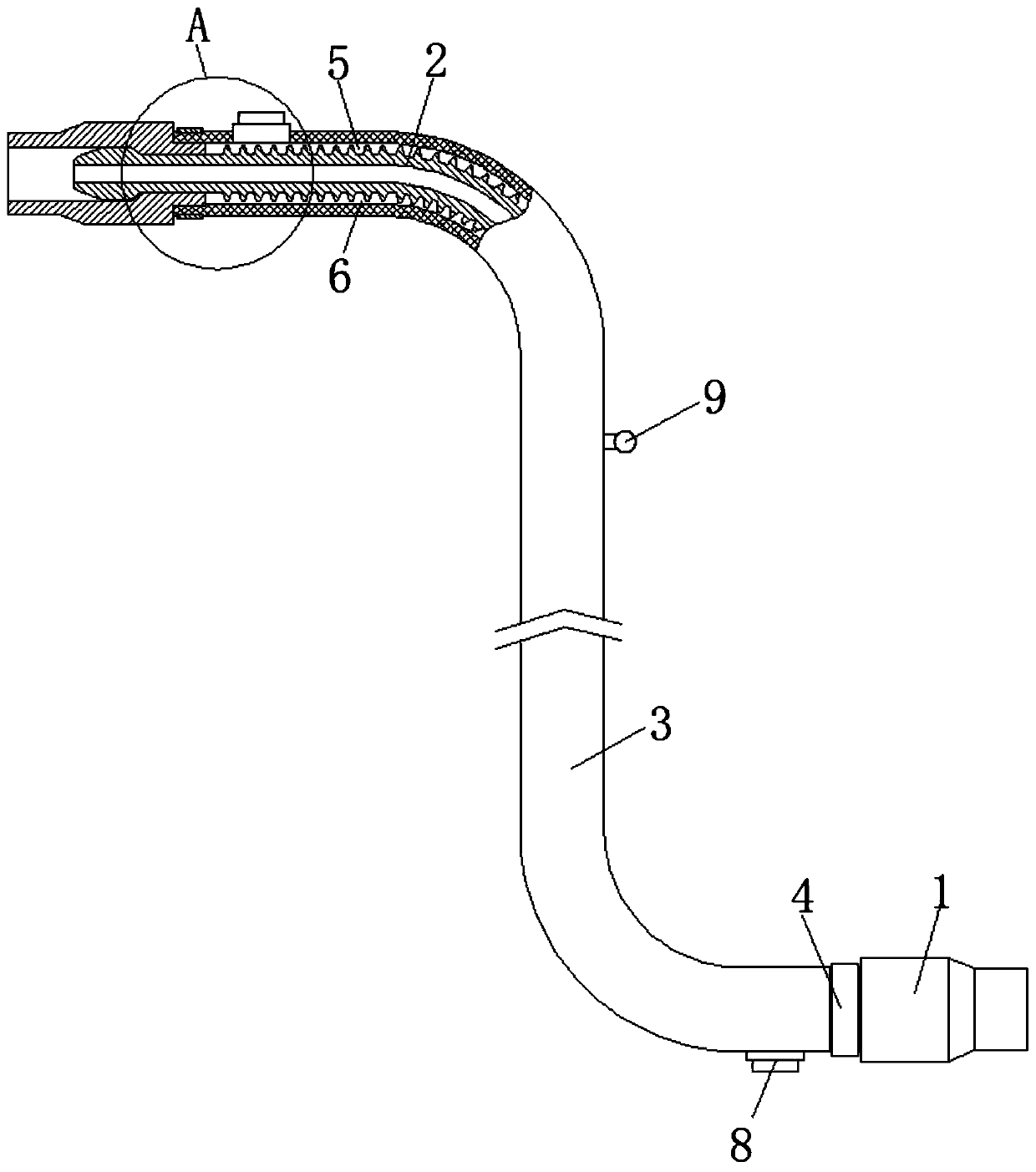
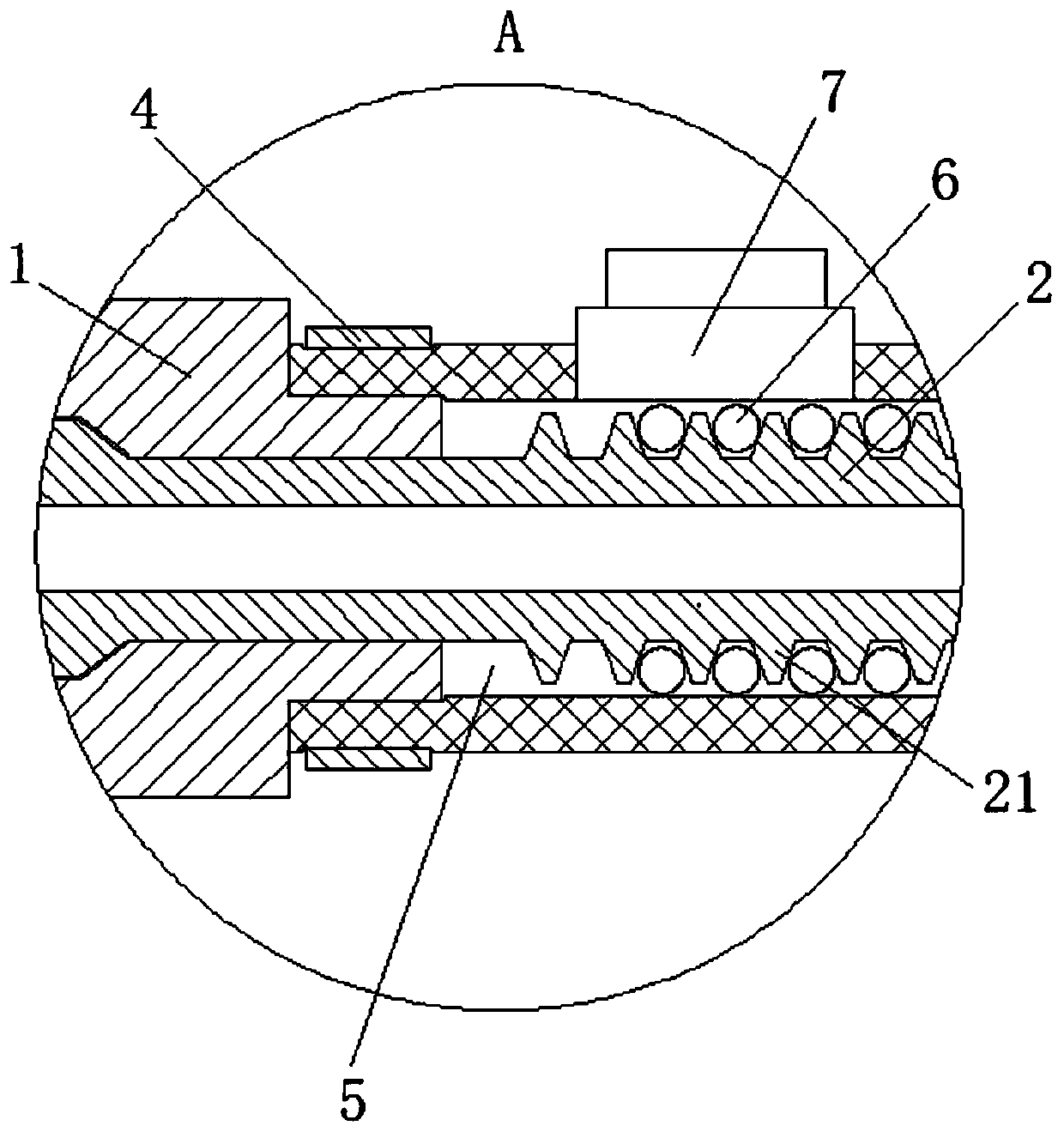
[0023] see figure 1 , a high-pressure oil pipe with a composite structure of the present invention, comprising a double-layer oil pipe and two joints 1, the double-layer oil pipe includes an inner layer oil pipe 2 and an outer layer casing 3, and the two ends of the inner layer oil pipe 2 are provided with upsetting heads. The head is set in the joint 1, the outer casing 3 is sleeved on the inner oil pipe 2, and the two ends of the outer casing 3 are respectively sleeved on the two joints 1, and the outer casing 3 is a high-pressure steel wire braided rubber hose. The outer casing 3 is clamped on the joint 1 through the clamp 4 sleeved on the outer casing 3, and a filling space 5 is preset between the outer casing 3 and the inner oil pipe 2; the filling space 5 is filled with filling 6, the outer sleeve 3 is provided with two through holes, and the filling valve 7 and the discharge valve 8 are fixedly installed on the two through holes respectively. When working, the discharge...
Embodiment 2
[0025] see figure 1 , a high-pressure oil pipe with a composite structure of the present invention, comprising a double-layer oil pipe and two joints 1, the double-layer oil pipe includes an inner layer oil pipe 2 and an outer layer casing 3, and the two ends of the inner layer oil pipe 2 are provided with upsetting heads. The head is set in the joint 1, the outer casing 3 is sleeved on the inner oil pipe 2, and the two ends of the outer casing 3 are respectively sleeved on the two joints 1, and the outer casing 3 is a high-pressure steel wire braided rubber hose. The outer casing 3 is clamped on the joint 1 through the clamp 4 sleeved on the outer casing 3, and a filling space 5 is preset between the outer casing 3 and the inner oil pipe 2; the filling space 5 is filled with filling 6, the outer sleeve 3 is provided with two through holes, and the filling valve 7 and the discharge valve 8 are fixedly installed on the two through holes respectively. When working, the discharge...
Embodiment 3
[0027] see figure 1 , a high-pressure oil pipe with a composite structure of the present invention, comprising a double-layer oil pipe and two joints 1, the double-layer oil pipe includes an inner layer oil pipe 2 and an outer layer casing 3, and the two ends of the inner layer oil pipe 2 are provided with upsetting heads. The head is set in the joint 1, the outer casing 3 is sleeved on the inner oil pipe 2, and the two ends of the outer casing 3 are respectively sleeved on the two joints 1, and the outer casing 3 is a high-pressure steel wire braided rubber hose. The outer casing 3 is clamped on the joint 1 through the clamp 4 sleeved on the outer casing 3, and a filling space 5 is preset between the outer casing 3 and the inner oil pipe 2; the filling space 5 is filled with filling There are two through holes on the outer casing 3, and the filling valve 7 and the discharge valve 8 are respectively fixedly installed on the two through holes. The filling material 6 is cooling ...
PUM
 Abstract
Description
Claims
Application Information
 - R&D
- Intellectual Property
- Life Sciences
- Materials
- Tech Scout
- Unparalleled Data Quality
- Higher Quality Content
- 60% Fewer Hallucinations
Browse by: Latest US Patents, China's latest patents, Technical Efficacy Thesaurus, Application Domain, Technology Topic, Popular Technical Reports.
© 2025 PatSnap. All rights reserved.Legal|Privacy policy|Modern Slavery Act Transparency Statement|Sitemap|About US| Contact US: help@patsnap.com