Supercharge Your Innovation With Domain-Expert AI Agents!

A grid sealing structure with self-adjusting grid stack gap

A sealing structure and self-adjusting technology, applied in the direction of engine seals, mechanical equipment, engine components, etc., can solve the problems of increased leakage, narrow operating temperature range, and inability to self-adjust when the gap increases, so as to achieve the effect of small leakage.

Active Publication Date: 2020-09-29
TSINGHUA UNIV +1
View PDF9 Cites 0 Cited by
  • Summary
  • Abstract
  • Description
  • Claims
  • Application Information

AI Technical Summary

Problems solved by technology

In the prior art, the grid plate adopts a regular hexahedral shape, and the formed gas film is of equal thickness. According to the derivation of the Reynolds equation of compressible fluid, its pressure distribution has nothing to do with the thickness of the gas film, that is, the gas film has no stiffness, so in When the working temperature changes or is disturbed by the axial direction, the gap between the grid plates increases and cannot be adjusted by itself. The gap is concentrated between one or two grid plates, resulting in a sharp increase in leakage. There are problems of narrow operating temperature range and poor anti-disturbance ability

Method used


Image

  • A grid sealing structure with self-adjusting grid stack gap
  • A grid sealing structure with self-adjusting grid stack gap
  • A grid sealing structure with self-adjusting grid stack gap

Examples


Embodiment 1

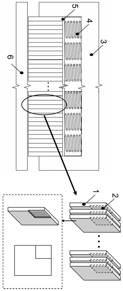
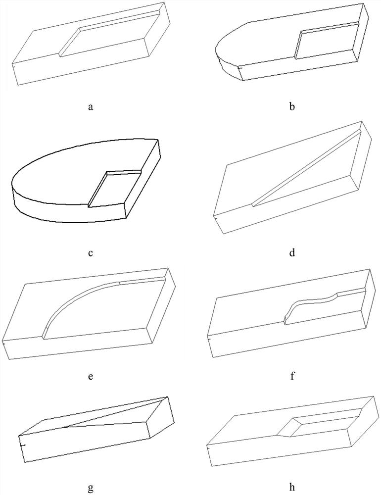
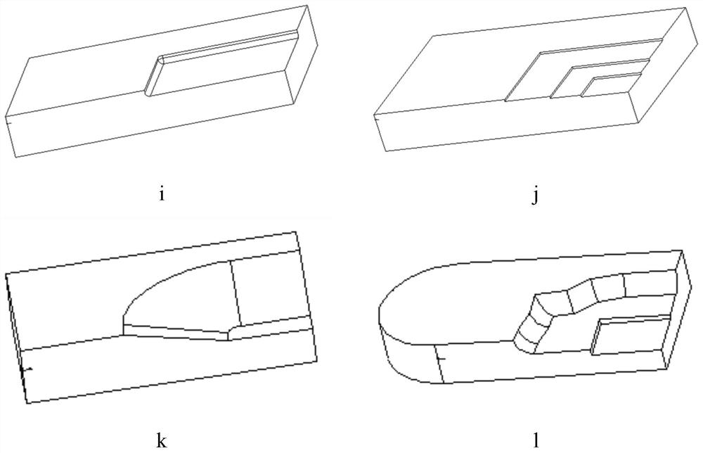
[0030] refer to figure 1 , image 3 , assuming that the figure 2 As shown in a, if one corner of the grid plate has a rectangular groove shape, the projected shape of the gas film produced after stacking is rectangular, and the high-voltage side has a projection with a rectangular projection surface, where the thickness of the raised part is the thickness of the step 2 Δh , which is constant, and the thickness without protrusions is the grid spacing h0, which is variable. When the area of ​​the grid is 12×20mm, and the area of ​​the step 2 is 6×10mm, the sealed high-pressure side is the adjacent two boundaries (Set left and upper), the pressure is 0.8MPa, the low-pressure side is located at the right boundary, and the length of 3.5mm connected to the lower boundary, the pressure is 0.1MPa, at the right boundary and the lower boundary, the square of the pressure is linearly related to the position, Then the relationship between the air film force and the grid gap h0 is shown...

Embodiment 2

[0032] refer to figure 1 , Figure 4 , Figure 4 Shown is the geometric model of the RBCC binary inlet, the fixed wall 10 and the movable plate 8 are connected by a hinge 7, and the space enclosed forms a variable flow channel 9. The grid plate structure of the present invention is installed on the movable flat plate 8 and contacts with the side wall to form a sealing structure. The rotation angle of the hinge 7 is small and the speed is slow. Therefore, the sealing structure can be regarded as a linear sealing structure moving in parallel. The leakage of the grid sealing structure is proportional to the cube of the gap, that is, Therefore, the leakage rate is particularly sensitive to clearance changes. Take the temperature change as an example: the material of the grid plate is generally a high temperature resistant composite ceramic material, and the material of the wall surface of the flow channel and the grid plate installation groove 3 is generally a high temperature...


PUM


Abstract

The invention discloses a grid plate seal structure with a grid plate stacking gap capable of being subjected to self-adjusting. The structure comprises grid plates, downwards-concave steps with the micron dimension thickness are machined on one faces of the grid plates, the grid plates with the machining faces consistent in orientation are stacked and mounted in a mounting groove, a grid plate seal structure of a non-uniform-thickness air film can be formed, and the steps are close to the high-pressure side of the grid plate seal structure. The air film with the ladder thicknesses is formed between the grid plates, due to the fluid hydrostatic effect, the air film has certain rigidity, the gap between the grid plates can be adjusted, the gap is automatically and uniformly distributed, theuniform-distribution gap has the minimum leakage amount, and therefore, under the same work temperature span, the leakage amount is greatly reduced, and the axial disturbance resistance capacity is reduced greatly.

Description

technical field [0001] The invention belongs to the technical field of grid plate sealing, and in particular relates to a grid plate sealing structure with self-adjusting grid stacking gaps. Background technique [0002] According to existing literature [Jeffrey J.DeMange, Patrick H.Dunlap, Bruce M.Steinetz, GaryJ.Drlik and Analex Corporation, "An Evaluation of High Temperature AirframeSeals for Advanced Hypersonic Vehicles," NASA / TM—2007-215043, AIAA– 2007–5743, October 2007], [Bruce M.Steinetz, "High Temperature Performance Evaluation of a Hypersonic Engine Ceramic Wafer seal", NASA-TM-103737, N91-22567], grid seal structure for a variable channel A linear sliding seal. In the prior art, the grid plate adopts a regular hexahedral shape, and the formed gas film is of equal thickness. According to the derivation of the Reynolds equation of compressible fluid, its pressure distribution has nothing to do with the thickness of the gas film, that is, the gas film has no stiffne...

Claims


Application Information

Patent Timeline
Patent Type & Authority Patents(China)
IPC IPC(8): F16J15/40
CPCF16J15/40
Inventor 黄伟峰刘莹李国志李永健李德才王玉明廖传军陈海鹏
Owner TSINGHUA UNIV
Features
  • R&D
  • Intellectual Property
  • Life Sciences
  • Materials
  • Tech Scout
  • Unparalleled Data Quality
  • Higher Quality Content
  • 60% Fewer Hallucinations
Learn More