Spatial structure balance weight device for reflector antennas

A space structure and balance weight technology, applied in the direction of antennas, antenna parts, electrical components, etc., can solve the problems that the reflective surface antenna cannot be connected or matched, the A-E type mount is not applicable, and the reflective surface antenna cannot be connected. The effects of mass production, stable mechanical properties, and balanced wind loads

Pending Publication Date: 2019-10-01
NO 54 INST OF CHINA ELECTRONICS SCI & TECH GRP
View PDF3 Cites 0 Cited by
  • Summary
  • Abstract
  • Description
  • Claims
  • Application Information

AI Technical Summary

Problems solved by technology

[0005] (2) Low stiffness
Since the pitch gear is a plane structure, when the counterweight is placed on it, it will increase the load of the gear and reduce the rigidity of the gear, thus affecting the accuracy of the transmission system
[0006] (3) Difficult to adjust
This utility model patent is only applicable to X-Y mounts of small-diameter reflector antennas, but not applicable to widely-used A-E mounts, especially large and medium-diameter reflector antennas
[0009] (2) Only the X axis is balanced
[0012] (1) Unable to connect to the reflector antenna
The methods provided by the above two utility model patents are only applicable to rod antenna forms such as base stations, and cannot be connected or matched with reflector antennas
[0013] (2) Not suitable for reflector antennas that rotate
The reflector antenna needs to move in pitch during work. The counterweights mentioned in the above two utility model patents are connected to the building through brackets or bases, and the pitching motion cannot be realized, so it is not suitable for rotating motion. reflector antenna

Method used


Image

  • Spatial structure balance weight device for reflector antennas
  • Spatial structure balance weight device for reflector antennas
  • Spatial structure balance weight device for reflector antennas

Examples


Embodiment Construction

[0045] The present invention will be further described below in conjunction with the accompanying drawings and specific embodiments.

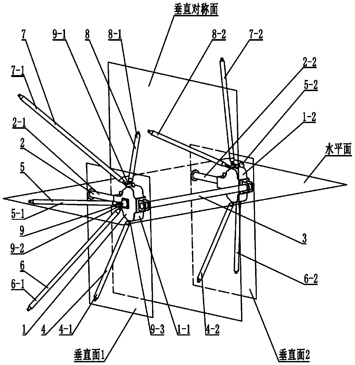
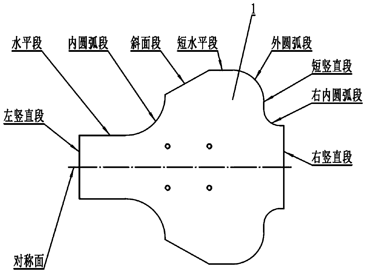
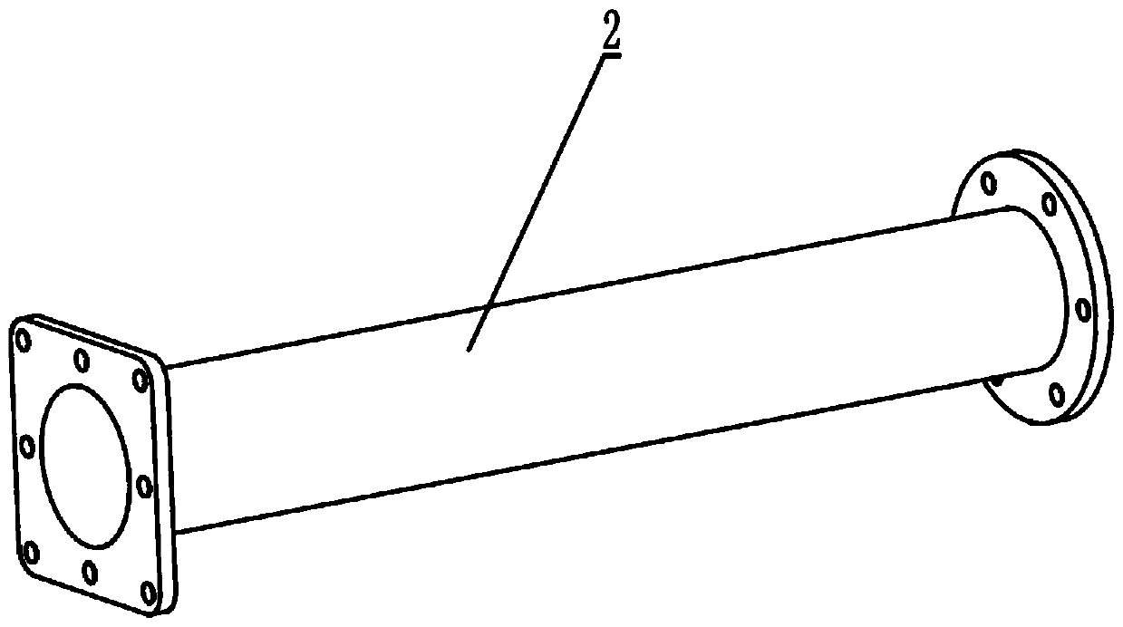
[0046] A space structure balance weight device for a reflector antenna, which includes two counterweight bodies on the left and right. The counterweight bodies have a symmetrical structure up and down. The front part of the counterweight body is narrow and the rear part is enlarged. The two sides of each counterweight body are For the windward side, the two counterweights are connected by beams. Each counterweight is equipped with a main support rod and an auxiliary support structure. The two counterweights, two main support rods and two sets of auxiliary support structures are relatively The vertical plane of the beam is mirror symmetrical;

[0047] The front end of the counterweight body has a front vertical surface, the front upper part of the counterweight body expansion part has an upper slope with the normal direction pointing forward and...


PUM


Abstract

The invention discloses a spatial structure balance weight device for reflector antennas, which relates to a design technology of a balance weight device for reflector antennas in the fields such as communication, measurement and control, and radio astronomy. The invention aims to provide a balance weight structure which has high rigidity and is light, easy to install and suitable for mass production. The balance weight device includes counterweight bodies, main supporting rods, a cross beam, vertical supporting rods, lateral supporting rods, lateral lower supporting rods, lateral upper supporting rods, inner supporting rods, ball joints, and the like. The shape of the counterweight device is symmetric. The two counterweight bodies are supported by a number of rods to form a stable spatialstructure. The spatial rods are connected with the counterweight bodies by bolt balls. The balance weight device has the characteristics of high structural rigidity and low weight, can balance part of wind load, reduces the disturbance of wind load to antennas, improves the operation accuracy of the antenna system, and is especially suitable for the balance weight structures in large and medium-sized reflector antennas.

Description

technical field [0001] The invention relates to the technical field of large and medium-diameter reflector antennas, in particular to a spatial structure balance weight device for reflector antennas. Background technique [0002] Reflector antennas used in the fields of communication, measurement and control, and radio astronomy must have a pitch function, and the pitch axis should coincide with the center of gravity of the pitch rotation part, so that the pitch moment of inertia and pitch wind moment are small. However, in the design process, it is generally impossible for the position of the center of gravity of the pitching and rotating part to coincide with the pitching axis. [0003] In order to reduce the load on the driving device and reduce the servo error, a balancing device is usually required. The traditional method is to install the balance weight in the box of the pitch device or place the balance weight on both sides of the pitch gear, so that the pitch rota...

Claims


Application Information

Patent Timeline
Patent Type & Authority Applications(China)
IPC IPC(8): H01Q1/00H01Q3/04H01Q19/12
CPCH01Q1/00H01Q1/005H01Q3/04H01Q19/12
Inventor 刘国玺杜彪郑元鹏赵均红杨晋蓉伍洋陈隆张一凡
Owner NO 54 INST OF CHINA ELECTRONICS SCI & TECH GRP
Why Eureka
Try Eureka