
Circuit module and method for manufacturing circuit module

A technology of circuit module and manufacturing method, which is applied in the direction of printed circuit manufacturing, circuit, printed circuit, etc., and can solve problems such as difficulty in miniaturization

Active Publication Date: 2019-10-01
MURATA MFG CO LTD
View PDF9 Cites 0 Cited by
  • Summary
  • Abstract
  • Description
  • Claims
  • Application Information

AI Technical Summary

Problems solved by technology

Due to the above-mentioned requirements, in the structure of the circuit module 300 described in Patent Document 1, it is difficult to miniaturize

Method used


Image

  • Circuit module and method for manufacturing circuit module
  • Circuit module and method for manufacturing circuit module
  • Circuit module and method for manufacturing circuit module

Examples


no. 1 approach -

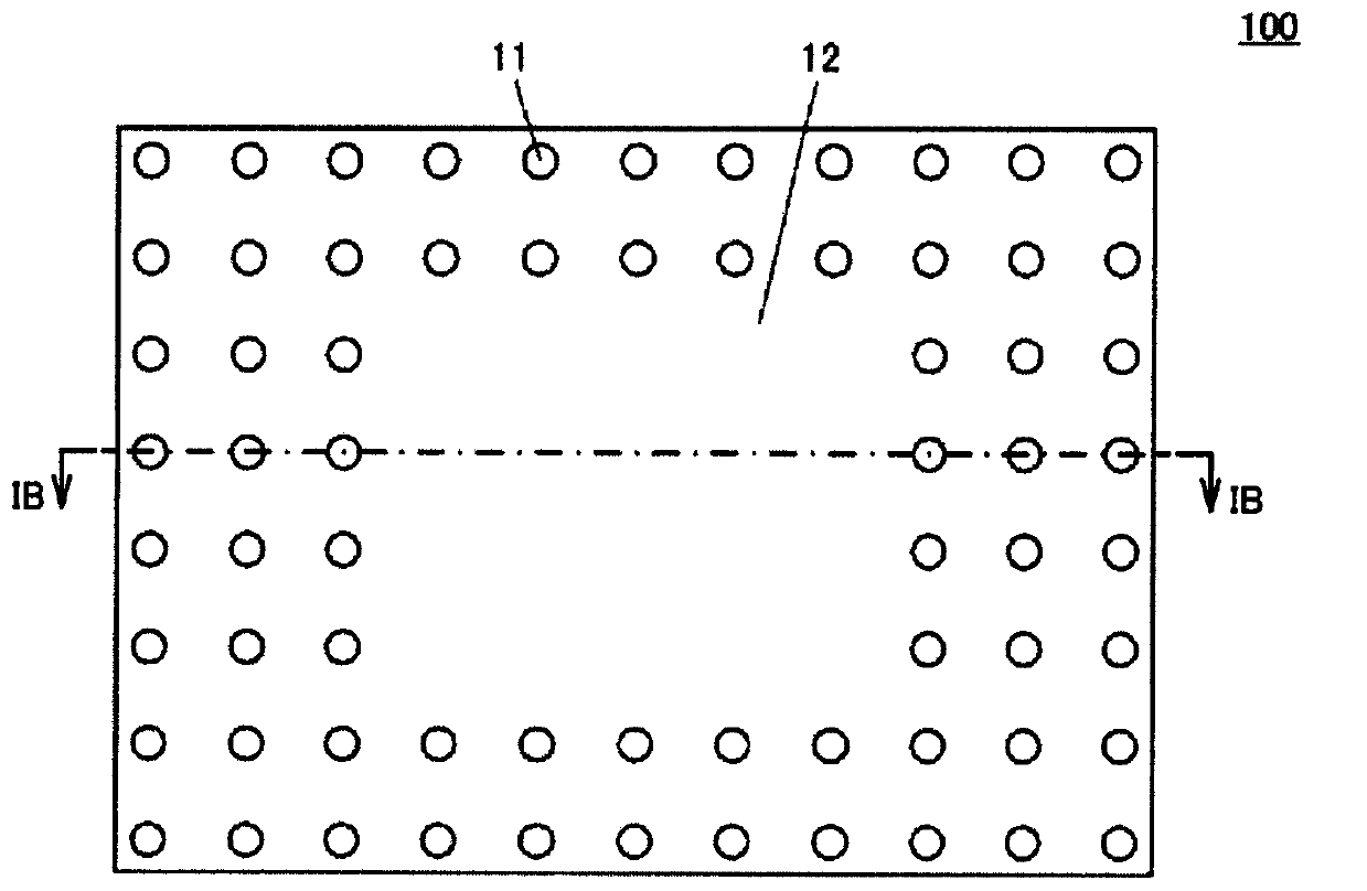
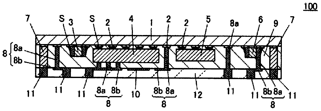
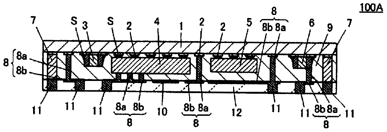
[0059] use Figure 1A ~ Figure 3B A first embodiment of the circuit module according to the present invention will be described. In addition, the drawings show only main parts, and mention and illustration of other parts are omitted for simplicity. In addition, only main parts are shown similarly about the following drawings.

[0060] In addition, in the drawings, the configuration and form of the circuit block and each component are schematic. That is, even if the configuration and form of the drawings used later are different from the actual circuit block, it can be said that the actual circuit block is essentially shown.

[0061]

[0062] Figure 1A ~ Figure 1B It is a figure explaining the structure of the circuit module 100 which is 1st Embodiment of the circuit module concerning this invention. Figure 1A It is an external view (bottom view) seen from the second resin layer 12 side in the direction normal to one main surface of the substrate 1 . Figure 1B yes F...


PUM


Abstract

A circuit module (100) is provided with: a substrate (1), one main surface of which is provided with a first wiring pattern (2); first electronic components (3-6) that constitute a first electronic circuit with the first wiring pattern (2); a plurality of connecting conductive bodies (8); a plurality of external connection terminals; a first resin layer (9); and a second resin layer (12). At leastone of the connecting conductive bodies (8) includes: a first columnar conductive body (8a) extending in the normal line direction of the one main surface of the substrate (1); and a board-like conductive body (8b) extending in the direction parallel to the one main surface of the substrate (1). At least one of the external connection terminals is a second columnar conductive body (11) extendingin the normal line direction of the one main surface of the substrate (1). The cross-sectional area of the first columnar conductive body (8a), said cross-sectional area being orthogonal to the normalline direction of the one main surface of the substrate (1), is smaller than the cross-sectional area of the second columnar conductive body (11), said cross-sectional area being orthogonal to the normal line direction of the one main surface of the substrate (1).

Description

technical field [0001] This invention relates to a circuit module including a substrate, an electronic component connected to the substrate to form an electronic circuit, an external connection terminal, a connection conductor connecting the electronic circuit and the external connection terminal, and a resin layer. Background technique [0002] There is known a circuit module including a substrate, electronic components connected to the substrate to form an electronic circuit, metal posts connected to the substrate, and a resin layer. An example of such a circuit module includes a circuit module described in International Publication No. WO2013 / 035714 (Patent Document 1) (corresponding to Japanese Patent No. 5768888). [0003] Figure 6 It is a cross-sectional view of the circuit module 300 described in Patent Document 1. FIG. Such as Figure 6 As shown, the circuit module 300 has a substrate 301 , electronic components 303 to 305 constituting an electronic circuit, metal ...

Claims


Application Information

Patent Timeline
Patent Type & Authority Applications(China)
IPC IPC(8): H01L23/12H01L21/56H01L21/60H01L23/29H01L23/31H01L25/04H01L25/18
CPCH01L2924/19105H01L21/56H01L23/12H01L25/04H01L25/18H01L2224/16225H01L23/3121H01L23/293H05K1/097H05K1/11H05K1/182H05K3/30H05K3/40H05K3/4644H05K2201/0257H05K2203/013
Inventor 佐藤和茂头岛淳江下雄也天知伸充
Owner MURATA MFG CO LTD
Learn More