Four limb fracture annular banding and fixing assisting machine

An auxiliary device and cerclage technology, applied in the direction of fixators, internal fixators, internal bone synthesis, etc., can solve the problems of inability to disassemble, local cerclage angle cannot be adjusted, single application site, etc., and achieve the effect of avoiding violent injuries

Pending Publication Date: 2019-10-08
吴杰洲
View PDF8 Cites 0 Cited by
  • Summary
  • Abstract
  • Description
  • Claims
  • Application Information

AI Technical Summary

Problems solved by technology

[0003] The purpose of the present invention is to provide a cerclage fixation aid for limb fractures to solve the problems that the current cerclage fixation aid for limb fractures proposed in the above background technology cannot be disassembled, the local cerclage angle cannot be adjusted, and the application site is single.

Method used


Image

  • Four limb fracture annular banding and fixing assisting machine
  • Four limb fracture annular banding and fixing assisting machine
  • Four limb fracture annular banding and fixing assisting machine

Examples


Embodiment 1

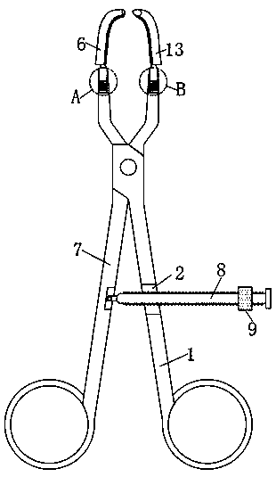
[0023] Such as Figure 1-4 , put the first handle 1 and the second handle 7 deep into the incision, and open the front ends of the first handle 1 and the second handle 7, so that the first embracing tube 6 and the second embracing tube 13 surround the fracture end, and then , twist the limit block 9, and move along the limit rod 8, so as to limit the opening angle of the tail ends of the first handle 1 and the second handle 7, and then pass the cable through the first encircling tube 6 and the The second embracing tube 13 can be cerclaged. Finally, the stop block 9 is twisted to loosen the first handle 1 and the second handle 7, and the first embracing tube 6 and the second embracing tube 13 are taken out.

Embodiment 2

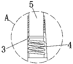
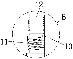
[0025] Such as Figure 1-5 , the first embracing tube 6 and the second embracing tube 13 are both arranged in an arc structure, and the front ends of the first embracing tube 6 and the second embracing tube 13 are both set in a pointed structure, according to the size of the incision and the fracture location, select a suitable arc and the first embracing pipe 6 and the second embracing pipe 13 of pipe diameter, and by the first connecting rod 5 and the second connecting rod 12, the first embracing pipe 6 and the second embracing pipe 13 are installed on the first handle 1 and the second embracing pipe 13 respectively. The upper end of the second handle 7 can be implemented by repeating Example 1 subsequently.

[0026] Working principle: When in use, according to the size of the incision and the location of the fracture, select the first embracing tube 6 and the second embracing tube 13 with appropriate curvature and tube diameter, and connect the first embracing tube 6 and th...


PUM


Abstract

The invention discloses a four limb fracture annular banding and fixing assisting machine. The four limb fracture annular banding and fixing assisting machine comprises a first handle and a second handle, wherein a through hole is formed in the first handle; a first connecting groove is formed in the upper end of the first handle; a first spring is vertically and fixedly mounted in the first connecting groove; a first connecting rod is propped against the upper end of the first spring; a first annular surrounding pipe is fixedly connected to the upper end of the first connecting rod; and a second annular surrounding pipe is fixedly connected to the upper end of a second connecting rod. According to the four limb fracture annular banding and fixing assisting machine disclosed by the invention, two groups of annular surrounding pipes being in a rotating threaded connection structure are arranged, so that disassembling and assembling are convenient; firstly, the two annular surrounding pipes are placed in a wound, and then a far end jaw device is mounted, so that the situation that the wound is extended by cutting is avoided; the two groups of annular surrounding pipes adopt designs of various different angles and different shapes, so that according to the wound and a fracture site, appropriate design is selected; moreover, when a cable smoothly penetrates out, the far end jaw device can be disassembled, so that the annular surrounding pipes in the wound can be smoothly taken out, and violet damage is avoided.

Description

technical field [0001] The invention relates to the field of surgical instruments, in particular to a cerclage fixation aid for limb fractures. Background technique [0002] Oblique fractures or comminuted fractures in the long bones of the extremities are often fixed with conventional plates and screws, and cable fixation is also required to achieve a better reduction and stability effect. However, this cable cerclage technique often requires more extensive incisions. It is necessary to expose the inner tissue of the fracture site as much as possible, so that the cable can avoid the obstruction of the soft tissue and pass through the opposite side smoothly, which not only increases the damage of the local soft tissue, destroys the blood supply of the local fracture site, and increases the possibility of infection, Especially in the femoral fracture cerclage process, the local tissue is rich, and the inner blood vessel and nerve are complicated. If a large-scale exposure is ...

Claims


Application Information

Patent Timeline
IPC IPC(8): A61B17/82
CPCA61B17/82
Inventor 吴杰洲蔡明卢广华刘鹏程孙琦李亘
Owner 吴杰洲
Why Eureka
Try Eureka