
Automatic football kicking machine

A ball machine, football technology, applied in sports accessories and other directions, can solve problems such as large differences, rigidity, and single training methods, and achieve the effect of balancing internal forces and reducing device vibration

Pending Publication Date: 2019-10-08
成都陆道原乡智能科技有限公司
View PDF1 Cites 4 Cited by
  • Summary
  • Abstract
  • Description
  • Claims
  • Application Information

AI Technical Summary

Problems solved by technology

[0002] In the field of modern football training, the training is often completed through the cooperation of team members, and very few have a ball machine for training. This not only requires a high number of players, but also makes it difficult to maintain the quality of artificial balls for a long time
Soccer ball machines have already been produced in the market, but the products are single and complicated, and the efficiency is low; for example, the patent document whose notification number is CN206214715U discloses a football ball machine. Symmetrically arranged rubber wheels (other existing soccer ball machines mostly use the serving method), the way of applying force is not humane enough, and the training method is relatively single and rigid; The instant concealment of the ball is relatively strong, and the dribbler cannot predict the timing of the serve in advance during training, which is quite different from when a real person plays.
In addition, the existing ball machine can not track the actual situation of the athletes on the training ground to meet the serve in each direction, so new requirements are put forward for the ball machine, which requires that the ball can be fired 360 degrees according to the movement state of the athlete, and more Intelligent to improve training efficiency and reduce costs
And the existing football ball machine basically does not have the function of picking up the ball automatically. After serving the ball, it needs to put all the balls back manually, which is time-consuming and laborious, and reduces the efficiency of serving the ball.

Method used


Image

  • Automatic football kicking machine
  • Automatic football kicking machine
  • Automatic football kicking machine

Examples


Embodiment Construction

[0036] In order to facilitate the understanding and implementation of the present invention, the preferred embodiments of the present invention are selected for further description in conjunction with the accompanying drawings.

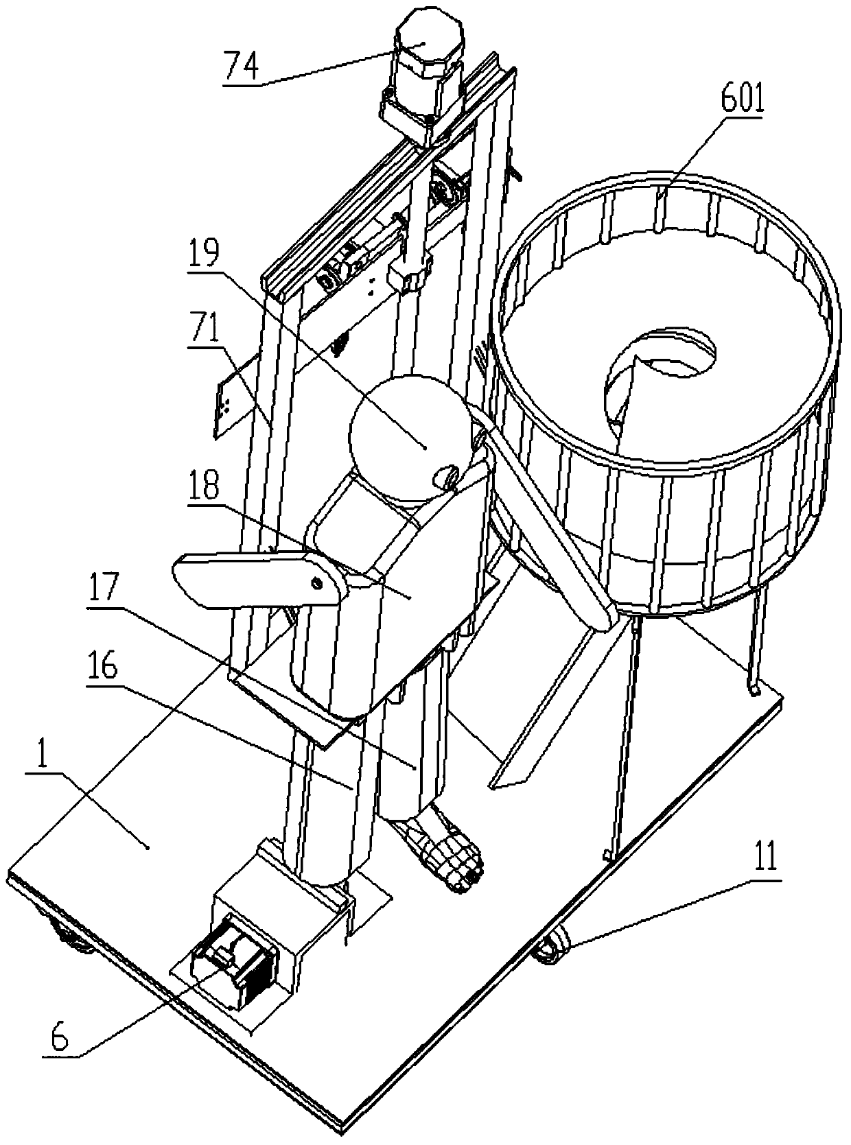
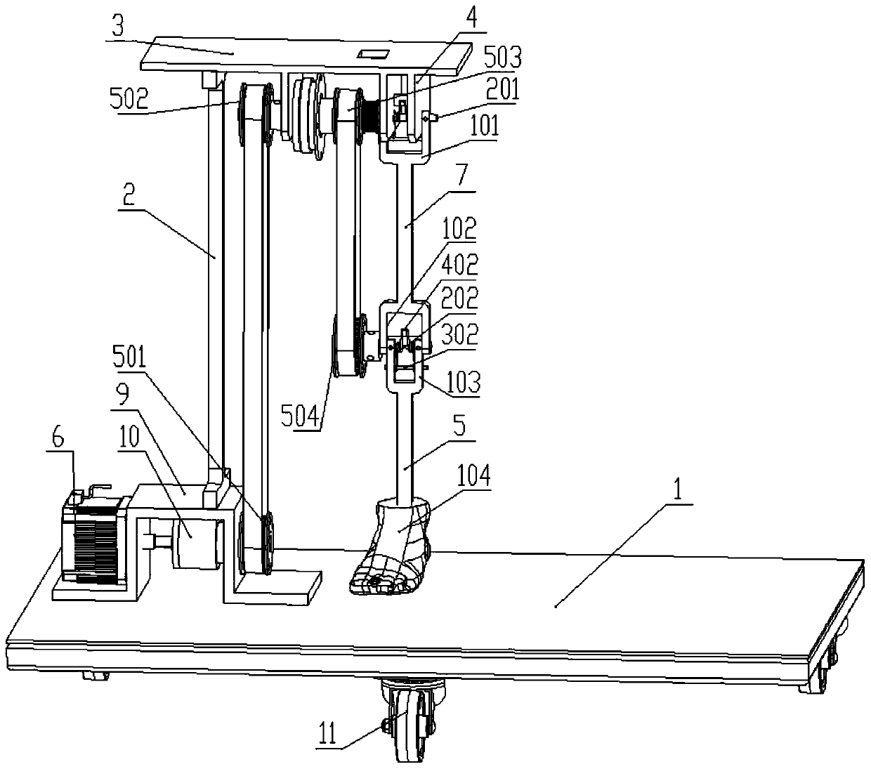
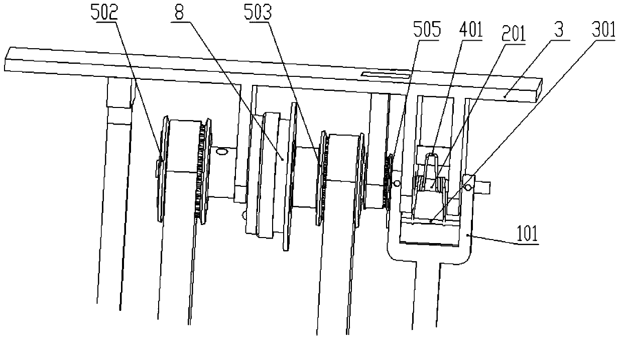
[0037] Such as Figure 1 to Figure 8 As shown, the present invention includes a base 1, the base 1 is fixedly provided with a support leg 2, and the top of the support leg 2 is fixedly provided with a horizontal beam 3, and one end of the horizontal beam 3 is suspended from the top of the support leg 2. The bottom of the overhanging end is provided with a bracket 4, and a horizontally arranged rotating shaft A201 is installed on the bracket 4. The rotating shaft A201 is connected to the drive motor 6 through the first transmission mechanism. The rotating shaft A201 is provided with a clutch 8 for controlling the rotation of the rotating shaft A201; The thigh frame 7 is fixedly connected.

[0038] A fixed shaft A301 is installed on the upper end of th...


PUM


Abstract

The invention relates to an automatic football kicking machine, and belongs to the technical field of football kicking machines. Power is transmitted to a rotating shaft A through a driving motor, a first transmission mechanism and a clutch, and then the power is transmitted to a thigh skeleton; the rotating shaft A and a rotating shaft B transmit the power through a transmission mechanism betweena rotating wheel C and a rotating wheel D, and then transmit the power to a crus skeleton; and torsional springs are mounted at the rotating shaft A and the rotating shaft B to store energy for ejecting a football. During ball kicking, the thigh skeleton and the crus skeleton can swing in the front-back direction, and finally the football is ejected by a ball kicking foot. The whole movement process of the thigh skeleton and the crus skeleton vividly simulates a ball kicking action of a real person, and a footballer can prejudge a ball kicking opportunity according to the ball kicking actionduring training, so that the training can be carried out in a ball kicking environment which is more accordant with the reality.

Description

technical field [0001] The invention relates to an automatic soccer ball serving machine, which belongs to the technical field of soccer ball serving machines. Background technique [0002] In the field of modern football training, the training is often completed through the cooperation of team members, and very few have a ball machine for training. This not only requires a high number of players, but also makes it difficult to maintain the quality of artificial balls for a long time. Soccer ball machines have already been produced in the market, but the products are single and complicated, and the efficiency is low; for example, the patent document whose notification number is CN206214715U discloses a football ball machine. Symmetrically arranged rubber wheels (other existing soccer ball machines mostly use the serving method), the way of applying force is not humane enough, and the training method is relatively single and rigid; The instant concealment of the dribbler is ...

Claims


Application Information

Patent Timeline
IPC IPC(8): A63B69/40A63B69/00
CPCA63B69/40A63B69/002
Inventor 董万福母银飞刘李逵林李柔李晓晓吴亮詹西岭
Owner 成都陆道原乡智能科技有限公司
Features
  • Generate Ideas
  • Intellectual Property
  • Life Sciences
  • Materials
  • Tech Scout
  • Unparalleled Data Quality
  • Higher Quality Content
  • 60% Fewer Hallucinations
Learn More