
Mechanical sealing device of high-speed high-pressure hydraulic pump

A mechanical seal device and hydraulic pump technology, applied in the field of mechanical hydraulics, can solve the problems of poor vibration and impact resistance, low rotation speed and sealing specific pressure, and poor reliability, so as to increase vibration and impact resistance and reduce specific power and specific pressure, increasing life and reliability effects

Pending Publication Date: 2019-10-08
XINXIANG HUAHANG AVIATION HYDRAULIC EQUIP
View PDF0 Cites 1 Cited by
  • Summary
  • Abstract
  • Description
  • Claims
  • Application Information

AI Technical Summary

Problems solved by technology

Low-speed and low-pressure hydraulic pumps generally use rotary shaft lip seals. Since the seals are made of rubber, the allowable rotation speed and sealing specific pressure of the rotary shaft lip seals are low, and cannot be used for high-speed high-pressure hydraulic pumps.
Although the traditional mechanical seals used in gear boxes, centrifuges and other equipment can be used in hydraulic pumps, traditional mechanical seals are generally composed of moving rings, static rings, springs, auxiliary sealing rings and other parts, and have complex structures and vibration resistance. The problem of poor shock performance, especially for high-speed and high-pressure hydraulic pumps, due to the obvious vibration and shock caused by high speed and high pressure, if the high-speed and high-pressure hydraulic pump uses traditional mechanical seals, the reliability is poor, the life is short, and it is easy to oil spill

Method used


Image

  • Mechanical sealing device of high-speed high-pressure hydraulic pump
  • Mechanical sealing device of high-speed high-pressure hydraulic pump
  • Mechanical sealing device of high-speed high-pressure hydraulic pump

Examples


Embodiment Construction

[0018] The technical solution of the present invention is further described below, but the scope of protection is not limited to the description.

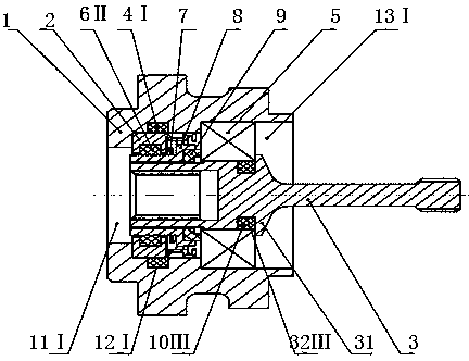
[0019] Such as figure 1 As shown, a mechanical seal device of a high-speed and high-pressure hydraulic pump includes a housing 1, a rear cover 2, and a transmission shaft 3. The housing 1 is provided with a through hole 11I, and the transmission shaft 3 is installed with a clearance fit with the through hole 11I. The housing 1 The inner side is provided with a ring groove 12I, the rubber sealing ring 4I is placed in the ring groove 12I, the back cover 2 is installed in the position near the front end of the casing 1, the outer side of the back cover 2 is closely attached to the rubber sealing ring 4I, and the casing 1 The rear end is provided with a counterbore 13I, the outer ring of the deep groove ball bearing 5 is installed with an interference fit with the counterbore 13I13, and the inner ring of the bearing 5 is installed with...


PUM


Abstract

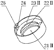
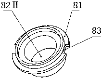
The invention discloses a mechanical sealing device of a high-speed high-pressure hydraulic pump. The mechanical sealing device comprises a shell body, a rear cover and a transmission shaft; the innerside of the shell body is provided with an annular groove I, and a rubber sealing ring I is arranged in the annular groove I; the rear end of the shell body is provided with a counter bored hole I, the outer ring of a bearing is in interference fit with the counter bored hole I, and the inner ring of the bearing is interference fit with the transmission shaft; the front end of the rear cover is provided with a through hole II, the inner side of the through hole II is provided with an annular groove II, a rubber sealing ring II is arranged in the annular groove II, the rear end of the rear cover is provided with a counter bored hole II, and an elastic element is installed in the counter bored hole II; the rear end of a supporting frame is provided with a flange, and the front end surface of the flange is closely attached to the elastic element; a sealing ring is movably connected with the supporting frame, the front end surface of the sealing ring is closely attached to the rear end surface of the flange, and the rear end surface of the sealing ring is closely attached to the front end surface of the inner ring of the bearing. The elastic element is used for providing compensationelastic force, it is ensured that the supporting frame, the sealing ring and the bearing are closely attached, and the mechanical sealing device has the characteristics of being simple in structure, good in sealing performance, resistant to high rotation speed and vibration impact, high in reliability, long in service life and the like.

Description

technical field [0001] The invention relates to the technical field of mechanical hydraulics, in particular to a mechanical seal device of a high-speed and high-pressure hydraulic pump. Background technique [0002] In order to improve the power density of high-pressure hydraulic pumps, hydraulic pumps are gradually developing towards high speed and high pressure. However, high speed and high pressure have brought about sealing problems. Since the transmission shaft runs through the inside and outside of the hydraulic pump, there is a circumferential gap between the transmission shaft and the hydraulic pump casing, and the hydraulic oil inside the hydraulic pump will leak out through this gap, so a sealing device must be installed at the end of the transmission shaft to prevent leakage . Low-speed and low-pressure hydraulic pumps generally use rotary shaft lip seals. Since the seals are made of rubber, the allowable rotation speed and sealing specific pressure of the rotary...

Claims


Application Information

Patent Timeline
Patent Type & Authority Applications(China)
IPC IPC(8): F16J15/16F16J15/26F16J15/32
CPCF16J15/16F16J15/26F16J15/32
Inventor 付永冬郭亭亭
Owner XINXIANG HUAHANG AVIATION HYDRAULIC EQUIP
Learn More