
Lighting apparatus for vehicles

一种照明装置、车辆的技术,应用在照明装置、照明装置的零部件、信号装置等方向,能够解决制造技术耗费大等问题,达到校准耗费减少的效果

Active Publication Date: 2019-10-08
HELLA KG HUECK & CO
View PDF8 Cites 3 Cited by
  • Summary
  • Abstract
  • Description
  • Claims
  • Application Information

AI Technical Summary

Problems solved by technology

However, the manufacturing technology for providing additional components is relatively expensive

Method used


Image

  • Lighting apparatus for vehicles
  • Lighting apparatus for vehicles
  • Lighting apparatus for vehicles

Examples


Embodiment Construction

[0018] The lighting device according to the invention for a vehicle is preferably designed as a headlight which is installed in the front region of the vehicle.

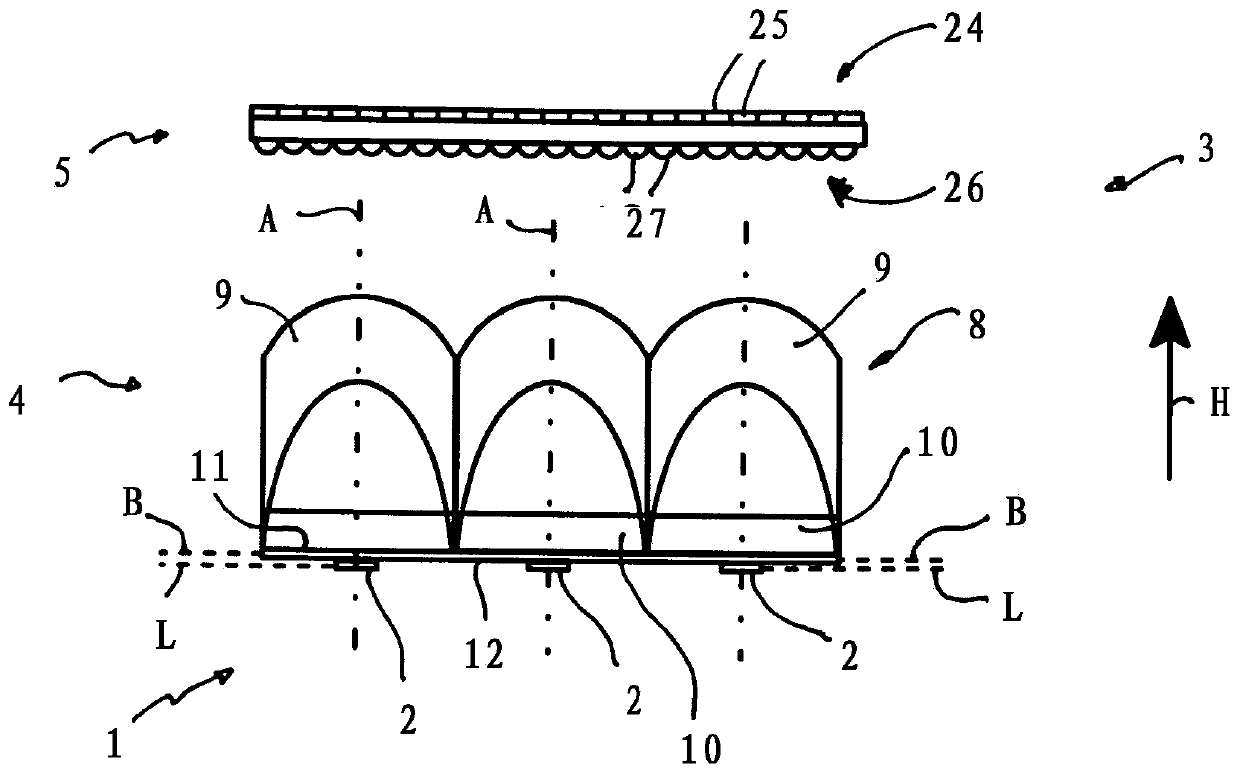
[0019] The lighting device has a light source unit 1 with a plurality of light sources 2 . The light sources 2 are designed as LED light sources, which are applied as light source chips on a circuit board (not shown).

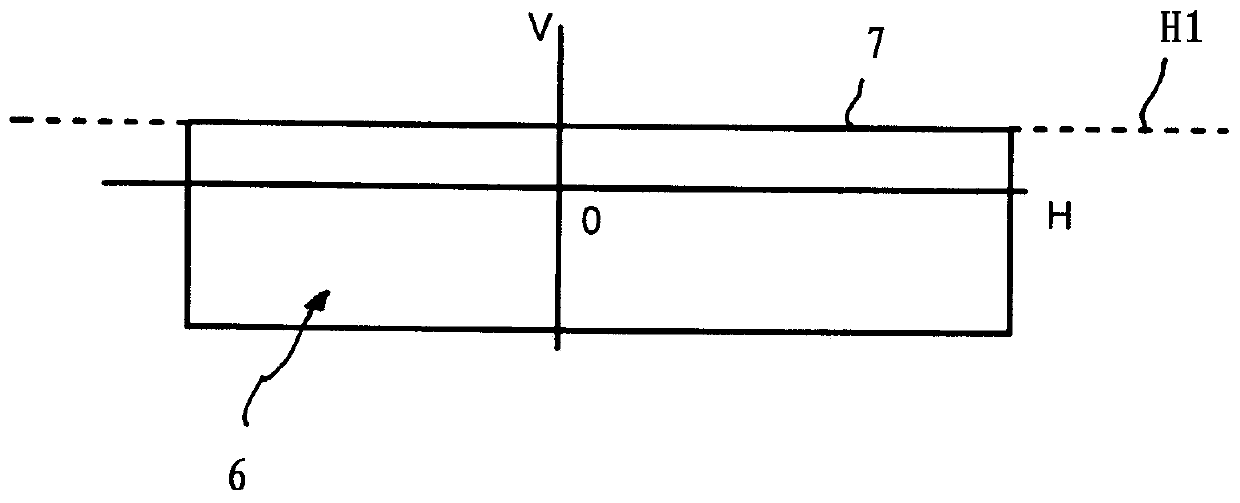
[0020] An optical unit 3 is arranged in front of the light source unit 1 in the main emission direction H, which essentially consists of an illumination optics 4 and a projection optics 5 . The illumination optics 4 serve to parallelize the light emitted by the light source 2 . The projection optics 5 is designed such that the light from the illumination optics 4 is redirected according to a predetermined light distribution. In the present exemplary embodiment, the projection optics 5 is designed in such a way that the output according to image 3 Symmetrical dipped beam distribution 6 with bright / ...


PUM


Abstract

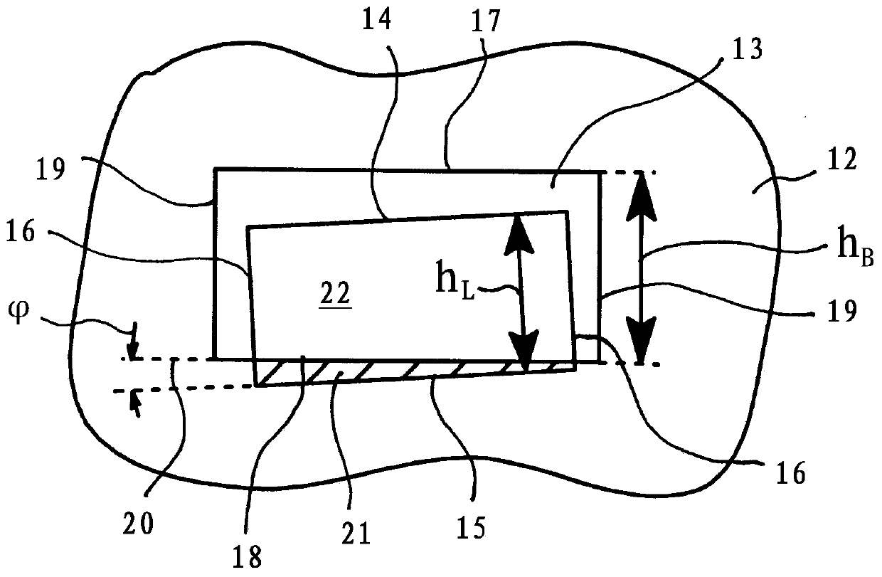
A lighting apparatus for vehicles having a light source unit containing a number of light sources, having an optical unit disposed in front of the light source unit in the main emission direction andcontaining a number of optical elements for imaging the light source according to a predetermined light distribution, having an additional element containing a cutout for the light source, wherein theadditional element is designed as an adjustment screen and the cutout as a screen opening, wherein the adjustment screen extends in a screen plane extending perpendicular to an optical axis of the optical unit between a light input face of the optical unit and a light source plane accommodating the light source, the light source has a contour, extending in the light source plane with light sourceedges which delimit a light-emitting face of the light source.

Description

technical field [0001] The invention relates to a lighting device for a vehicle comprising a light source unit comprising a number of light sources, an optical unit arranged in front of the light source unit in a main emission direction and an additional element comprising a cutout for the light source, The optical unit contains a certain number of optical elements in order to image the light source according to a predetermined light distribution. Background technique [0002] A lighting device for vehicles is known from DE 10 2013 107 355 A1, comprising a light source unit and an optical unit arranged in front of the light source unit in the main emission direction for generating a predetermined light distribution. The light source unit includes, as light sources, LED light sources positioned on the light entrance side of the optical unit. These LED light sources are located in the objective plane for the light distribution to be generated, wherein the contour of the recta...

Claims


Application Information

Patent Timeline
Patent Type & Authority Applications(China)
IPC IPC(8): F21S41/43F21S41/10
CPCF21S41/10F21S41/43F21S41/143F21S41/151F21S41/19F21S41/26F21S41/275F21S41/285F21S41/29F21V5/04F21V11/08F21S41/265F21S41/40
Inventor F·波恩德F·保罗S·约尔格
Owner HELLA KG HUECK & CO
Learn More