Display system and binocular system

A technology of display system and spatial light modulator, applied in optical elements, optics, instruments, etc., can solve the problems of high cost, unfavorable application, difficult technology realization, etc., and achieve the effect of simple structure

Active Publication Date: 2019-10-08
SHANGHAI INTELIGHT ELECTRONICS TECH CO LTD
View PDF8 Cites 11 Cited by
  • Summary
  • Abstract
  • Description
  • Claims
  • Application Information

AI Technical Summary

Problems solved by technology

[0003] The working principle and structure of the existing display systems with light fields and different image depths are relatively complicated, technically difficult to realize, and costly, which is not conducive to application in real life

Method used


Image

  • Display system and binocular system
  • Display system and binocular system
  • Display system and binocular system

Examples


Embodiment

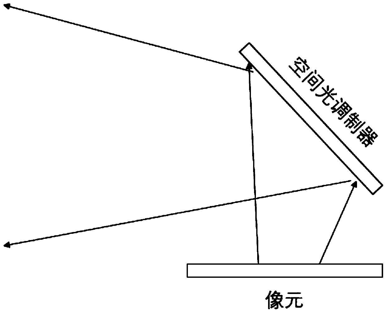
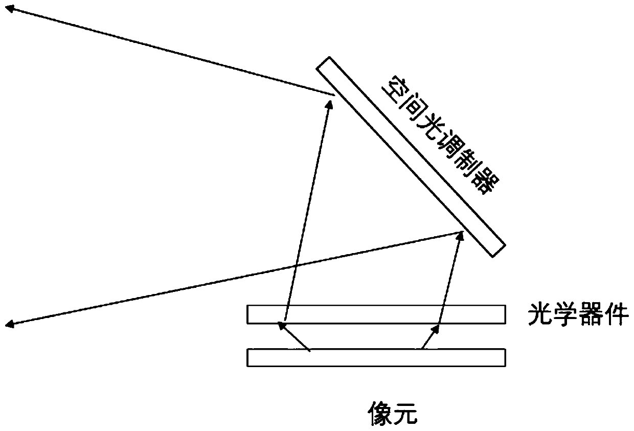
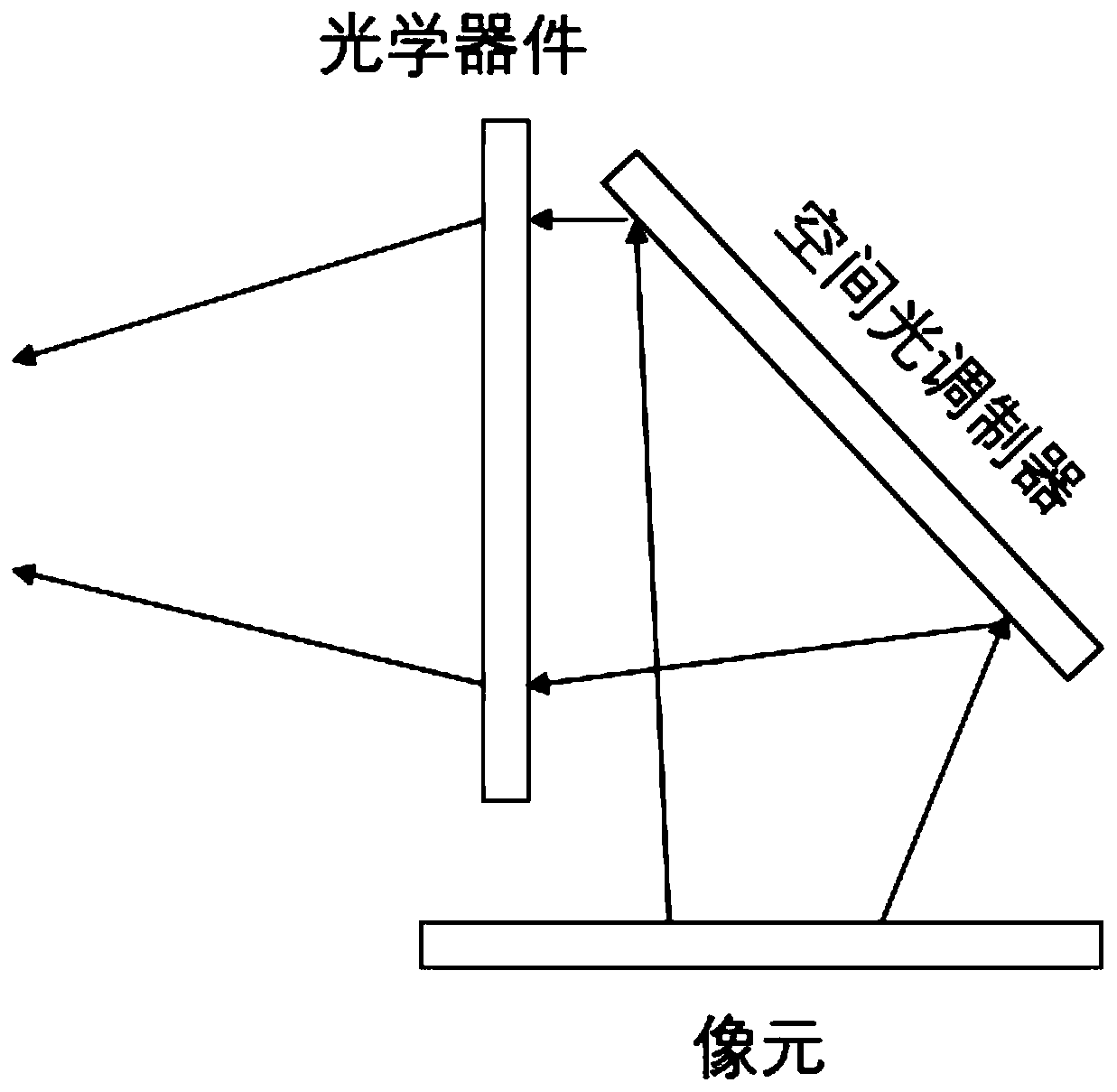
[0065] A display system such as figure 2 As shown, including pixels, using OLED screen, resolution 1920x1080, spatial light modulator is a reflective phase modulation silicon-based liquid crystal device, adopts ECB mode liquid crystal package, pixel size is 4.6um, shape is square, resolution 3840x2160 , the control circuit uses the CPU+ASIC solution. The system also includes a polarizer, which is arranged between the OLED and the spatial light modulator, and is used for modulating the polarization direction of the image light emitted by the OLED to be consistent with the direction required by the spatial light modulator. A grating waveguide is also included in the system to expand the image output by the spatial light modulator (pupil expansion).

[0066] The role of each part is as follows:

[0067] The OLED screen generates an image, and the image adopts a time-division multiplexing method, that is, the control circuit controls to output only a specific color (band) in RG...


PUM


Abstract

The invention provides a display system and a binocular system. The display system comprises a pixel, a spatial light modulator and a control circuit. Light outputted by the pixel enters the spatial light modulator obliquely; and the light is modulated by the spatial light modulator and then the modulated light is outputted. The control circuit is respectively connected to the pixel and the spatial light modulator to control an image displayed by the pixel and control a modulation signal of the spatial light modulator. The pixel displays different focal lengths respectively by corresponding todifferent parts of the spatial light modulator. According to the invention, the display system has a simple structure; and the pixel corresponds to different parts of the spatial light modulator, thereby displaying different focal lengths to realize a 3D visual effect.

Description

technical field [0001] The invention relates to the field of optical display devices, in particular to a display system and a binocular system. Background technique [0002] The invention patent with the publication number CN105700320A discloses a holographic three-dimensional display method and device based on a spatial light modulator. The directional diffraction screen constitutes. Obtain the multi-view two-dimensional image of the target object, and generate a set of image arrays for phase hologram calculation after the preprocessing transformation process. The iterative Fourier transform algorithm is used to calculate the corresponding phase hologram, and the hologram is loaded into the spatial light modulator, and the hologram is illuminated by a laser light source to obtain a holographic reconstruction image. Design and manufacture a directional diffraction screen based on a pixel-type nano-grating, and directional diffract the corresponding reproduced image pixels ...

Claims


Application Information

Patent Timeline
Patent Type & Authority Applications(China)
IPC IPC(8): G02B27/22
CPCG02B30/27
Inventor 谈顺毅
Owner SHANGHAI INTELIGHT ELECTRONICS TECH CO LTD
Why Eureka
Try Eureka