Punch for hot air pressure forming of metal pipe

A technology of metal pipe fittings and punches, which is applied in the field of punches for hot air forming of metal pipe fittings, can solve problems such as high noise and safety, and achieve the effect of avoiding safety hazards, reducing safety hazards, and ensuring the effect of noise reduction

Active Publication Date: 2019-10-11
DALIAN UNIV OF TECH
View PDF6 Cites 0 Cited by
  • Summary
  • Abstract
  • Description
  • Claims
  • Application Information

AI Technical Summary

Problems solved by technology

[0006] The present invention aims to solve the problem of large noise and unpredictability when a large amount of high-pressure or ultra-high-pressure gas is discharged from the narrow gap between the pipe end and the punch during the inflation process and exhaust process of the existing metal pipe fittings. To solve the safety problem, a special punch that can achieve fast, stable and safe exhaust is designed

Method used


Image

  • Punch for hot air pressure forming of metal pipe
  • Punch for hot air pressure forming of metal pipe
  • Punch for hot air pressure forming of metal pipe

Examples


Embodiment 1

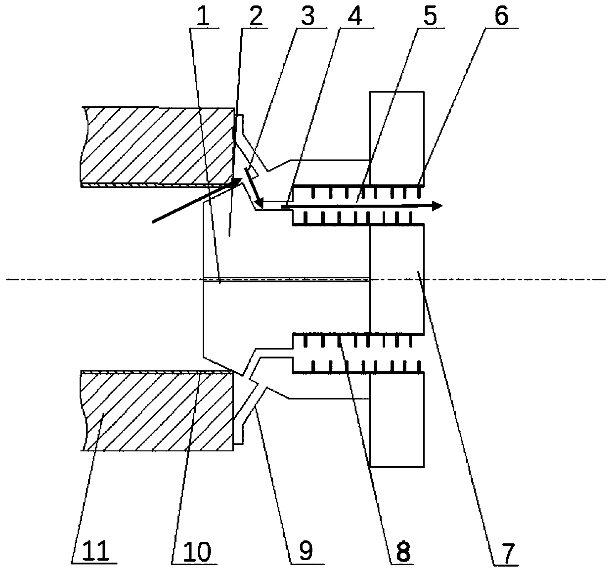
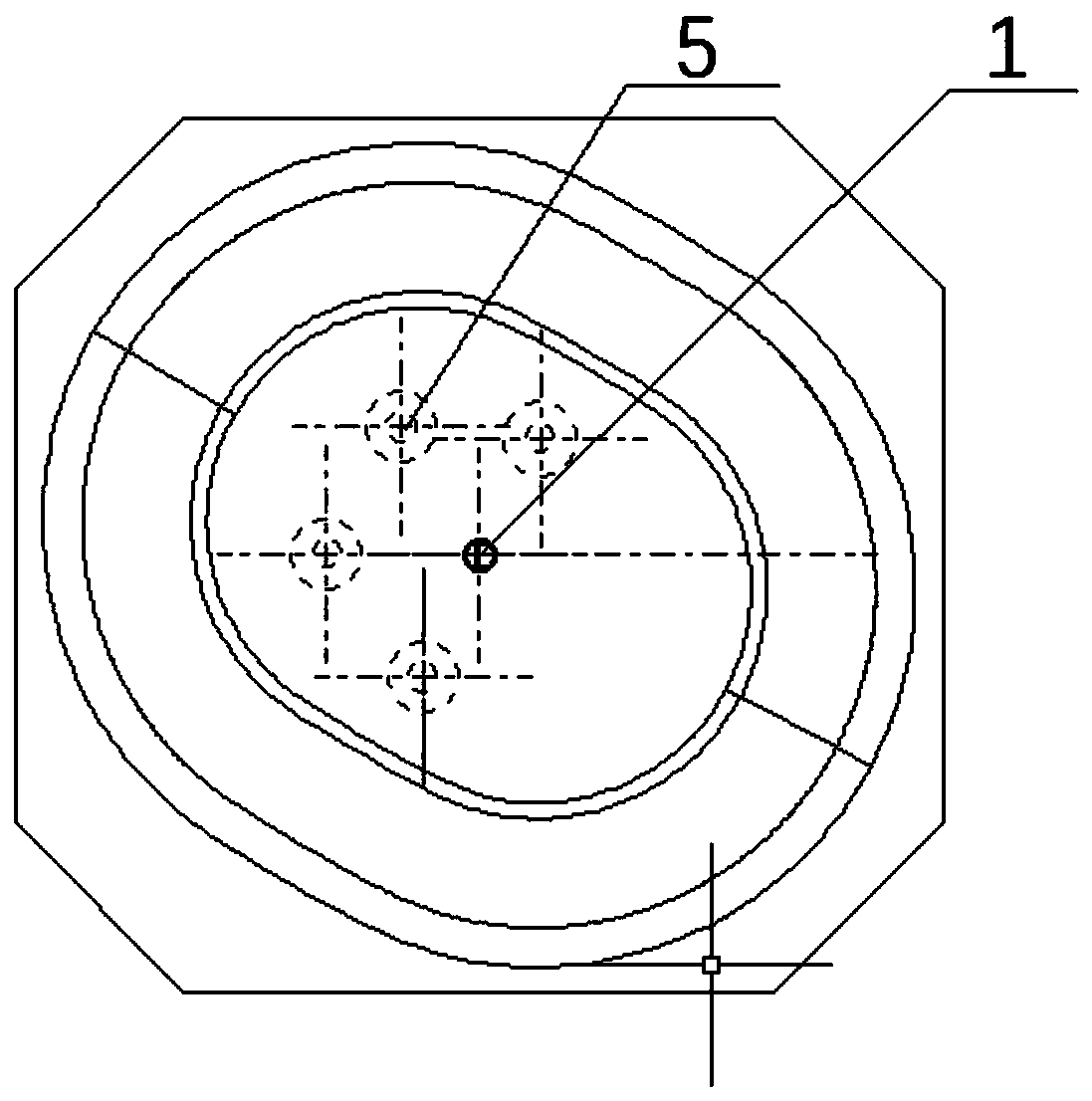
[0027] Example 1: Combining figure 1 , figure 2 and image 3 Description, a punch for hot air pressure forming of metal pipe fittings, including air inlet 1, punch cone 2, air chamber 3, exhaust pipe 4, anechoic chamber 5, two-component silencing cotton 6, flange 7. Silencer disc 8 and baffle plate 9.

[0028] The taper of the punch cone surface 2 is determined according to the diameter of the metal pipe 10. The length of the punch entering the metal pipe is 1 / 3 of the cone surface, and there is a baffle 9 perpendicular to the cone surface at 2 / 3 of the cone surface. In order to strengthen the air chamber To ensure the best sealing effect, the vertical section with a length of 3 cm protruding from the baffle is used to fit the mold.

[0029] An exhaust pipe 4 is arranged between the baffle plate 9 and the position where the punch enters the pipe material. The exhaust pipe 4 is divided into two sections, the first section is perpendicular to the punch cone surface 2, and th...

Embodiment 2

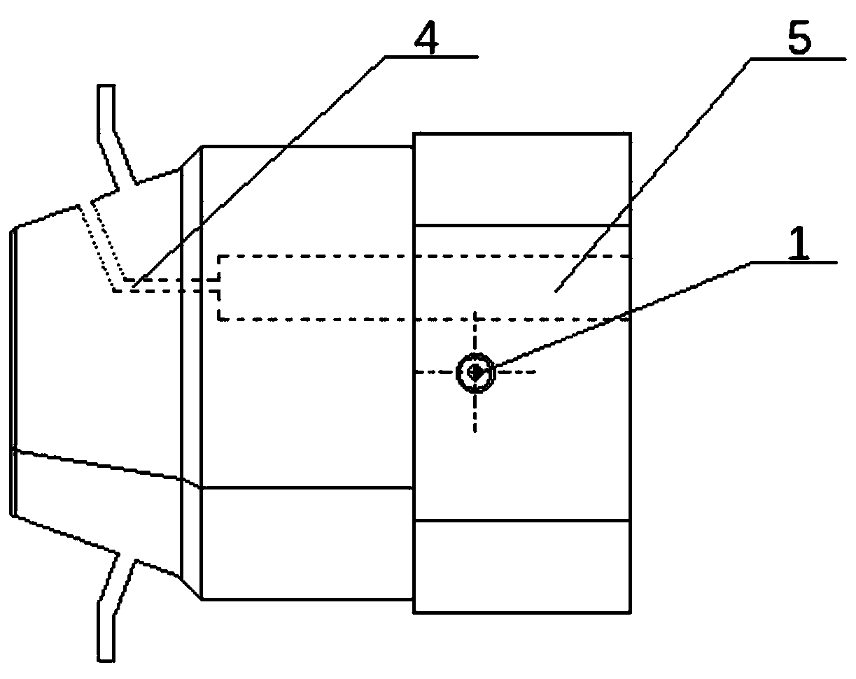
[0030] Embodiment 2: Combination figure 1 and Figure 4 Description It is suitable for local bulging of pipes. The cone surface 2 of the punch is determined according to the diameter of the metal pipe. The length of the punch entering the metal pipe 10 is 1 / 3 of the cone surface. Under the forming condition of no mold forming an air chamber, the baffle 9 is divided into three sections, the first section is a baffle plate perpendicular to the cone surface at 2 / 3 of the cone surface, the second section is parallel to the pipe, and the length is 50mm, and the third section is perpendicular to and in contact with the pipe. The air chamber 3 is formed, and the discharged high-temperature and high-pressure gas is introduced into the exhaust pipe 4 . Such setting increases the application range of the punch for hot air forming of metal pipe fittings.

Embodiment 3

[0031] Example 3: The two-component sound-absorbing cotton 6 of this embodiment is polyester sound-absorbing cotton, and the sound-absorbing cotton 6 and the inner wall of the sound-absorbing chamber are connected by rivets. With such a setting, it has good material stability, will not expand and shrink due to temperature changes, is convenient for maintenance, and has a good noise reduction effect. Others are the same as those in Embodiment 1 or 2.

[0032] Working process: 1: Gas collection: When the conical surface 2 of the sealing punch enters the 1 / 3 position of the metal pipe, the extended section of the baffle plate 9 and the mold 11 form an air chamber. In the case of exhaust, the high-temperature and high-pressure gas is discharged from the matching gap between the metal pipe and the sealing cone surface, enters the air chamber 3, and then enters the exhaust pipe 4.

[0033] 2. Muffling and exporting gas: high-temperature and high-pressure gas enters the muffler cham...


PUM


Abstract

The invention provides a punch for hot air pressure forming of a metal pipe. The punch comprises a punch conical surface, an air chamber, an exhaust pipe, a silencing chamber, two-component silencingcotton, a flange plate, a silencing disc and a baffle plate. The punch relates to a sealing punch for sealing high-temperature and high-pressure gas, and aims to solve the problems that in a present pipe inflating and forming, the high-pressure gas is discharged from a matched gap between a pipe blank and a punch, and large noise is generated due to the high flow rate and the large flow, and solvethe problem that potential safety hazards are generated due to the fact that the flowing direction of the gas is uncertain. The punch is used for guiding and silencing the high-pressure gas at the two ends during integral or local hot air pressure forming of the metal pipe.

Description

technical field [0001] The invention relates to a punch used for hot air pressure forming of metal pipe fittings, in particular to a punch structure capable of realizing safe exhaust and noise reduction during hot air pressure forming of metal pipe fittings. Background technique [0002] When metal pipe fittings are formed by hot air pressure, the original tube blank is first heated to a certain temperature through a high-temperature mold, so that the deformation ability of the material is improved, and the deformation resistance is significantly reduced. Then, high-pressure gas is filled into the hot tube blank, and the tube blank is bulging and deformed by using the high-pressure gas. The method overcomes the disadvantages of poor formability of the aluminum alloy material at room temperature and difficulty in forming complex parts. At the same time, the gas pressure required for forming is only 1 / 10 to 1 / 40 of normal temperature forming. At present, hot gas pressure for...

Claims


Application Information

Patent Timeline
Patent Type & Authority Applications(China)
IPC IPC(8): B21D26/045
CPCB21D26/045
Inventor 汤正英何祝斌杨姝亓昌苑世剑
Owner DALIAN UNIV OF TECH
Why Eureka
Try Eureka