Fiber bragg grating strain sensor

A strain sensor and fiber grating technology, applied in the field of sensors, can solve the problems of lack of elastic structure, harsh use environment of optical fiber, limited strain measurement range, etc., and achieve the effect of increasing the strain range, increasing the elastic sleeve and prolonging the service life.

Inactive Publication Date: 2019-10-11
杭州铭迦网络科技有限公司
View PDF0 Cites 0 Cited by
  • Summary
  • Abstract
  • Description
  • Claims
  • Application Information

AI Technical Summary

Problems solved by technology

The existing fiber grating strain sensor lacks elastic structure, resulting in limited strain measurement range, and the use environment of optical fiber is harsh, there is no way to protect it

Method used


Image

  • Fiber bragg grating strain sensor
  • Fiber bragg grating strain sensor
  • Fiber bragg grating strain sensor

Examples


Embodiment Construction

[0015] The following will clearly and completely describe the technical solutions in the embodiments of the present invention with reference to the accompanying drawings in the embodiments of the present invention. Obviously, the described embodiments are only some, not all, embodiments of the present invention. Based on the embodiments of the present invention, all other embodiments obtained by persons of ordinary skill in the art without making creative efforts belong to the protection scope of the present invention.

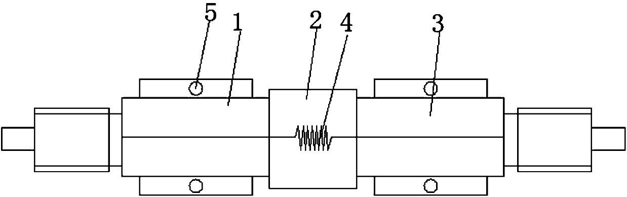
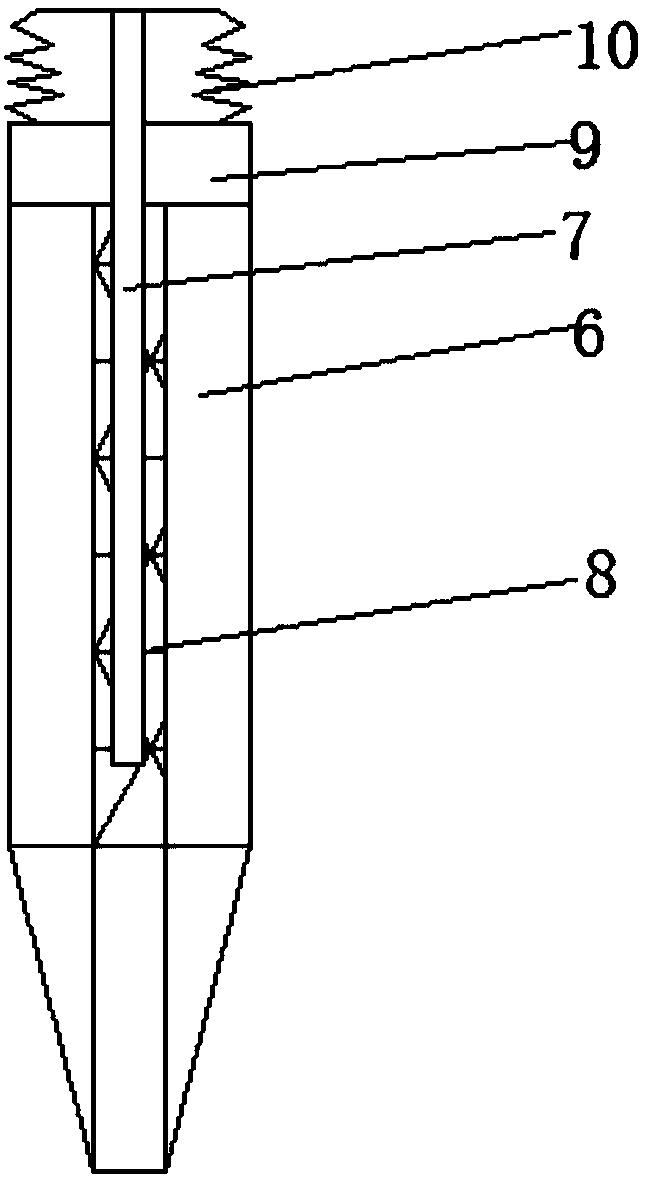
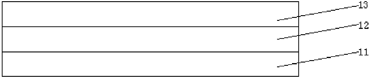
[0016] see Figure 1-4 , an embodiment provided by the present invention:

[0017] A fiber grating strain sensor, comprising a fixed metal sleeve one 1, a fixed metal sleeve two 3, an elastic sleeve 2, an optical fiber grating 4 and a fixing assembly, the fixed metal sleeve one 1 and the fixed metal sleeve two 3 One end is respectively sleeved on the two ends of the elastic sleeve 2 and the ends of the fixed metal sleeve one 1 and the fixed metal sleeve two 3...


PUM


Abstract

The invention discloses a fiber bragg grating strain sensor. According to the fiber bragg grating strain sensor, one end of a first fixed metal sleeve and one end of a second fixed metal sleeve are arranged at the two ends of an elastic sleeve respectively in a sleeving mode, a fiber bragg grating is fixed into the elastic sleeve, fixing screw holes of fixing components are fixed to the first fixed metal sleeve and the second fixed metal sleeve respectively, one end of each fixing bolt is of a conical structure, the fixing bolts are inserted into the corresponding fixing screw holes, a throughhole is formed in each fixing bolt, the end of each through hole communicates with the end of a cone head of the corresponding fixing bolt, a pushrod is inserted into the through hole of each fixingbolt, one end of each pushrod is also of a conical structure, each through hole is filled with viscous glue, and an anti-corrosion component is further arranged on each of the first fixed metal sleeve, the second fixed metal sleeve and the elastic sleeve. The fixing method of the fiber bragg grating strain sensor is easy and convenient to use, and service life is prolonged.

Description

technical field [0001] The invention relates to a sensor, in particular to a fiber grating strain sensor. Background technique [0002] Traditional strain sensors are based on strain-electricity, use electrical signals as the carrier of conversion and transmission, and use wires to transmit electrical signals. Therefore, they are easily affected by electromagnetic fields and the environment when used. If the humidity of the environment is too high, it may cause sensor damage. Short circuit, easy to cause fire in high temperature and flammable, explosive environment, etc. At the same time, electrical sensors cannot be used in series. When the number of sensors has a certain scale, it is necessary to lay a large number of signal transmission cables, and also require a corresponding scale of signal receiving and processing equipment, which increases the cost of use. In addition, due to the large number of electrical sensors Signals cannot be transmitted remotely, and a certain...

Claims


Application Information

Patent Timeline
Patent Type & Authority Applications(China)
IPC IPC(8): G01B11/16
CPCG01B11/16
Inventor 刘晓航刘益民
Owner 杭州铭迦网络科技有限公司
Why Eureka
Try Eureka