Eureka AIR delivers breakthrough ideas for toughest innovation challenges, trusted by R&D personnel around the world.

Solid-state laser radar and laser scanning system thereof

A technology of laser scanning and laser radar, which is applied in radio wave measurement system, electromagnetic wave re-radiation, utilization of re-radiation, etc., can solve problems such as single scanning form, large vibration influence, high price, etc., and achieve overcoming price and high stability , cost reduction effect

Inactive Publication Date: 2019-10-11
SHENZHEN LUBANG TECH CO LTD
View PDF0 Cites 2 Cited by
  • Summary
  • Abstract
  • Description
  • Claims
  • Application Information

AI Technical Summary

Problems solved by technology

[0003] The use of mechanical rotary scanning radar to realize vehicle-mounted laser scanning radar is expensive, and is greatly affected by vibration, poor stability, and single scanning form.

Method used


Image

  • Solid-state laser radar and laser scanning system thereof
  • Solid-state laser radar and laser scanning system thereof
  • Solid-state laser radar and laser scanning system thereof

Examples


Embodiment Construction

[0030] Reference will now be made in detail to the exemplary embodiments, examples of which are illustrated in the accompanying drawings. When the following description refers to the accompanying drawings, the same numerals in different drawings refer to the same or similar elements unless otherwise indicated. The implementations described in the following exemplary examples do not represent all implementations consistent with the present invention. Rather, they are merely examples of apparatuses and methods consistent with aspects of the invention as recited in the appended claims.

[0031] The following disclosure provides many different embodiments or examples for implementing different structures of the present application. To simplify the disclosure of the present application, components and arrangements of specific examples are described below. Of course, they are examples only and are not intended to limit the application. Furthermore, the application may repeat refe...


PUM


Abstract

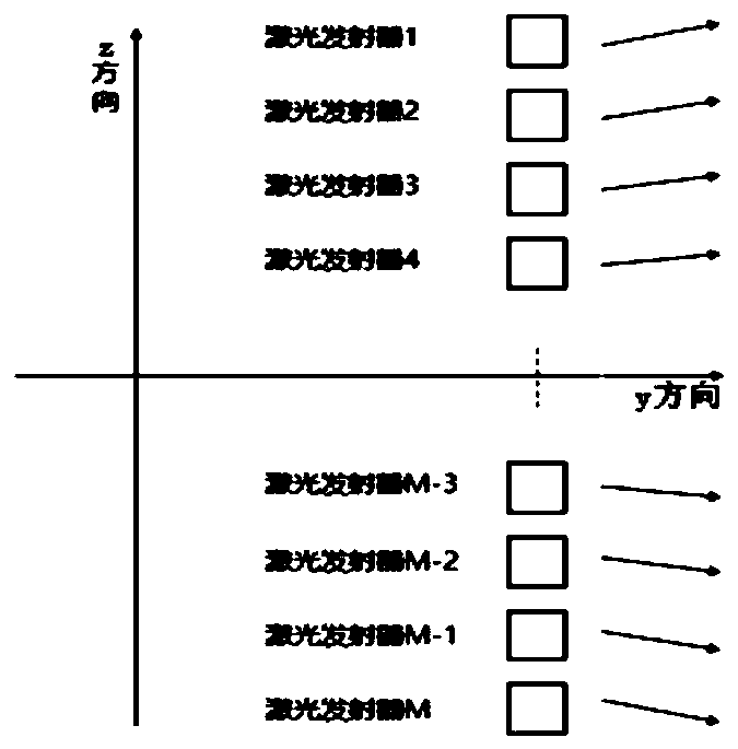
The application relates to a solid-state laser radar and a laser scanning system thereof. The solid-state laser radar is characterized by comprising a laser emitting array, wherein the laser emittingarray comprises M laser emitters, each laser emitter is used for emitting a beam of laser and used for forming M laser beams emitted from a y direction and distributed along a z direction; and a beamdeflection component group which comprises multiple bean deflection components arranged at an emitting direction of the laser emitting array and cascaded on the y direction vertical to the z directionand located in the xy plane, wherein the size of the multiple beam deflection components can cover the M laser beams, and the beam deflection components can be used for deflecting M laser beams.

Description

technical field [0001] The present application relates to the technical field of intelligent measurement and control devices, in particular to a solid-state laser radar and its laser scanning system. Background technique [0002] In recent years, with the rapid development of automobile intelligent driving technology, higher requirements have been put forward for vehicle laser scanning radar. [0003] The use of mechanical rotary scanning radar to realize vehicle-mounted laser scanning radar is expensive, and is greatly affected by vibration, poor stability, and single scanning form. Contents of the invention [0004] In order to overcome the problems existing in the related technologies, the present application provides a solid-state laser radar and a laser scanning system thereof. [0005] According to an embodiment of the present application, a laser scanning system of a solid-state lidar is provided, which is characterized in that it includes: [0006] A laser emitti...

Claims


Application Information

Patent Timeline
Patent Type & Authority Applications(China)
IPC IPC(8): G01S17/88G01S17/93G01S7/481
CPCG01S17/88G01S7/481G01S7/4817G01S17/931
Inventor 陈琪张礼朝李晓春
Owner SHENZHEN LUBANG TECH CO LTD
Why Eureka
Eureka Blog
Learn More