fuel injector

A fuel injector and fuel injection technology, applied in fuel injection devices, special fuel injection devices, charging systems, etc., can solve the problems of reducing the strength of the nozzle body and reducing the life of the nozzle body

Active Publication Date: 2021-11-05
ROBERT BOSCH GMBH
View PDF3 Cites 0 Cited by
  • Summary
  • Abstract
  • Description
  • Claims
  • Application Information

AI Technical Summary

Problems solved by technology

[0004] The configuration of cooling channels in the nozzle body results in a reduction in the strength of the nozzle body and thus in the lifetime of the nozzle body
Furthermore, existing fuel injectors without active cooling cannot be simply retrofitted to an embodiment with cooling channels

Method used


Image

  • fuel injector
  • fuel injector
  • fuel injector

Examples


Embodiment Construction

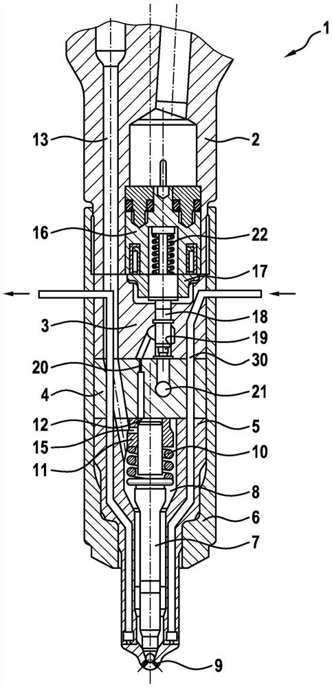
[0029] exist figure 1 A fuel injector 1 , as known from the prior art, for injecting fuel into a combustion chamber of an internal combustion engine is shown in longitudinal section.

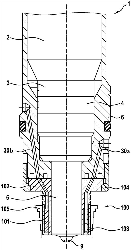
[0030] The known fuel injector 1 comprises an injector body 2 , a valve body 3 , an intermediate plate 4 and a nozzle body 5 . All these components are held together by the nozzle clamping nut 6 . In this case, the nozzle body 5 contains a nozzle needle 7 which is arranged longitudinally displaceable in a pressure chamber 8 formed in the nozzle body 5 . During the opening movement of the nozzle needle 7 , fuel is injected into the combustion chamber of the internal combustion engine via a plurality of injection openings 9 formed in the nozzle body 5 .

[0031] A flange can be seen on the nozzle needle 7, on which the compression spring 10 is supported. The other end of the compression spring 10 is supported on a control sleeve 11 , which in turn bears against the underside of the intermediate...


PUM


Abstract

The invention relates to a fuel injector (1) for injecting fuel into a combustion chamber of an internal combustion engine, wherein the fuel injector (1) comprises a nozzle body (5). A pressure chamber (8) is formed in the nozzle body (5), which can be supplied with fuel under pressure via an inflow opening (13). A longitudinally movable nozzle needle (7) which releases or closes at least one injection opening (9) is arranged in the pressure chamber (8). The cooling group (100) is arranged at least partially surrounding the nozzle body (5). The cooling group (100) comprises a cooling ring (101) which delimits a plurality, preferably more than 20 flow channels (200) through which flow can flow, for cooling the nozzle body (5).

Description

technical field [0001] The invention relates to a fuel injector. Background technique [0002] A fuel injector for injecting fuel into a combustion chamber of an internal combustion engine is known from EP1781931 B1. Known fuel injectors include an injector body and a nozzle body. Injector body and nozzle body are clamped to each other via the nozzle clamping nut. A pressure chamber is formed in the nozzle body, which can be supplied with fuel under pressure via the inflow opening. A longitudinally movable nozzle needle, which releases or closes the at least one injection opening, is arranged longitudinally movable in the pressure chamber. [0003] Furthermore, known fuel injectors have cooling channels or flow channels formed in the nozzle body. The cooling channel serves to cool the nozzle body and the nozzle needle exclusively in the area facing the combustion chamber. [0004] The formation of cooling channels in the nozzle body results in a reduction in the strengt...

Claims


Application Information

Patent Timeline
Patent Type & Authority Patents(China)
IPC IPC(8): F02M53/04
CPCF02M53/043F02M2200/855F02M2200/803
Inventor A·霍夫施泰特尔F·古根比希勒M·施瓦岑贝格尔S·帕塞达赫
Owner ROBERT BOSCH GMBH
Why Eureka
Try Eureka