Stable locking structure for drawer

A lock-off and drawer technology, which is applied to drawers, applications, household appliances, etc., can solve problems such as the falling of the connecting seat, affecting the stability of the drawer, and the inability to securely assemble the connecting seat, so as to improve the convenience of use and stability and solid, compact structure

Pending Publication Date: 2019-10-15
GUANGDONG DTC HARDWARE PRECISION MFG CO LTD
View PDF3 Cites 0 Cited by
  • Summary
  • Abstract
  • Description
  • Claims
  • Application Information

AI Technical Summary

Problems solved by technology

The locking separation device and the height adjustment device of this structure are respectively arranged on the connecting seat, and the connecting seat is fixed on the bottom plate of the drawer through fasteners. If the thickness of the bottom plate is small and not enough for the fasteners When it is functioning, the connecting seat cannot be assembled stably, causing the connecting seat to fall easily during use, which affects the stability of the drawer

Method used


Image

  • Stable locking structure for drawer
  • Stable locking structure for drawer
  • Stable locking structure for drawer

Examples


no. 1 example

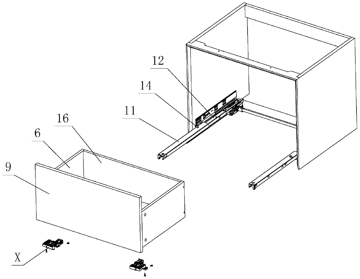
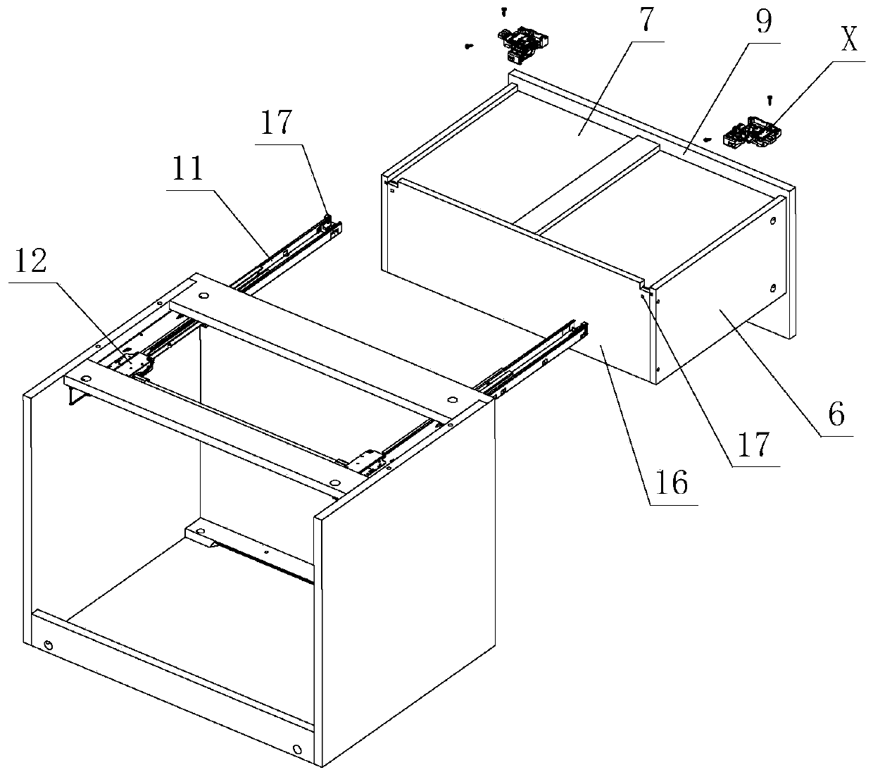
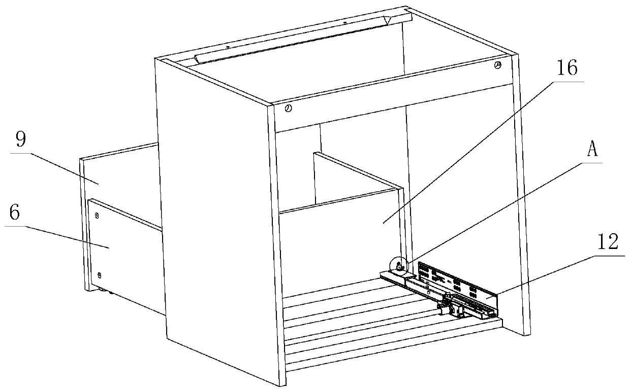
[0027] see Figure 1-Figure 9 , which is used for the stable lock-off structure of the drawer, including a lock-off device X, the lock-off device X at least includes a coupling seat 1, a front hole 30 is provided at the front of the coupling seat 1, and a front fastening part 2 is provided on the front hole 30, Side hole 31 is provided on the side of connection seat 1, and side fastening part 3 is arranged on side hole 31; 32 are perpendicular to each other.

[0028] Furthermore, the front hole 30 and the side hole 31 are set independently of each other, and a certain distance is formed between them; the front fastening part 2 and the side fastening part 3 are respectively set on the front hole 30 and the side hole 31 , and realize the fixing of different directions of the coupling seat 1.

[0029] Further speaking, the lateral extension of the coupling seat 1 is provided with a side wing 4, and a side step 5 is formed between the side wing 4 and the coupling seat 1; the sid...

no. 2 example

[0040] see Figure 10 , Figure 11 , which is used for the stable lock-off structure of the drawer, which is different from the first embodiment in that: the connecting seat 1 is provided with an elastic member 20 and a swing member 21; the buckling part 15 is arranged on the swing member 21; Among them, one end of the elastic member 20 is elastically arranged on the connecting seat 1, and the other end is elastically arranged on the swinging member 21. The swinging member 21 elastically swings on the connecting seat 1 through the elastic member 20, and when elastically swings, it passes through the buckle part 15 and The front connecting parts 13 are engaged with or disengaged from each other.

[0041] Other unmentioned parts are the same as the first embodiment.


PUM


Abstract

The invention discloses a stable locking structure for a drawer. The stable locking structure for the drawer comprises a locking device, the locking device at least comprises a connecting seat, a front hole is formed in the front part of the connecting seat, a front fastening part is arranged on the front hole, and a side hole is formed in the side part of the connecting seat; a side fastening part is formed in the side hole; wherein the front hole forms a certain acute angle with the bottom surface of the connecting seat, and the side hole and the bottom surface of the connecting seat are perpendicular to each other. The structure is improved and the mutual cooperation of the front fastening part and the side fastening part is utilized, so that the locking device is stably assembled on the furniture drawer, and the stability and the firmness of the mutual assembling of the locking device and the furniture drawer are improved so as to avoid the disadvantage that the locking device in the prior art can only be fixed to a bottom plate of the furniture drawer, and the practicability is high.

Description

technical field [0001] The present invention relates to a secure lock-off structure for drawers. Background technique [0002] Chinese Patent Document No. CN103610334B disclosed on April 6, 2016 a detachable locking adjustment mechanism for drawer slide rails, including a slide rail assembly for opening and closing a drawer, and a connecting seat arranged at the bottom of the drawer. There is a locking and separating device connected with the slide rail assembly, and a height adjusting device for adjusting the height of the drawer. The moving slide rail of the slide rail assembly is provided with a boss; the locking and separating device includes a locking lever, a lock The rod is rotatably arranged on the connecting seat, and the front end is provided with more than one level of steps, and through the steps, at least when the moving slide rail is assembled, it is locked and connected with the boss. , the anti-off baffle is connected with the boss at least when the moving s...

Claims


Application Information

Patent Timeline
IPC IPC(8): A47B88/427A47B88/49A47B88/57A47B88/919
CPCA47B88/427A47B88/49A47B88/57A47B88/919
Inventor 伍志勇
Owner GUANGDONG DTC HARDWARE PRECISION MFG CO LTD
Why Eureka
Try Eureka