Jet grouting pile construction process dynamic monitoring method

A technology of dynamic monitoring and jet grouting piles, which is applied in foundation structure engineering, foundation structure test, construction, etc., can solve problems such as irreparable waste of materials and difficulty in taking remedial measures, and achieve clear and intuitive monitoring results, suitable for popularization Apply, put in nondestructive effects

Active Publication Date: 2019-10-15
BEIJING ZHONGYAN DADI TECH CO LTD
View PDF4 Cites 4 Cited by
  • Summary
  • Abstract
  • Description
  • Claims
  • Application Information

AI Technical Summary

Problems solved by technology

Drilling and coring is the most direct and widely used monitoring method. It belongs to the posterior method. The pro

Method used


Image

  • Jet grouting pile construction process dynamic monitoring method

Examples


Example Embodiment

[0032] Example 1:

[0033] Using the monitoring method introduced by the present invention, a model test is carried out on a certain site, the jet grouting borehole depth is 15 meters, and the jet grouting pile diameter is 1.5 meters. The specific technology is as follows:

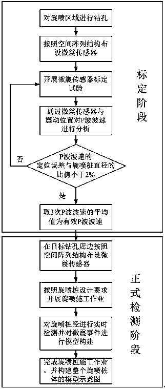
[0034] Such as figure 1 As shown, the dynamic monitoring method of the jet grouting pile construction process is characterized in that the method of dynamically monitoring the size of the pile diameter during the jet grouting pile construction process based on the microseismic sensor adopts the following steps:

[0035] Step 1: Drill holes in the jet grouting area, with a bore diameter of 130mm, and the drill hole spacing is 0.8 times the design value of the jet grouting pile diameter;

[0036] Step 2: After the drilling is completed, 20 microseismic sensors are arranged around the target borehole according to the spatial array structure. The horizontal distance between the microseismic sensors and the center of ...

Example Embodiment

[0053] Example 2:

[0054] Using the monitoring method introduced by the present invention, a model test is carried out at a certain site, the depth of the jet grouting pile is 10 meters, and the diameter of the jet grouting pile is 1.5 meters. The specific technology is as follows:

[0055] Such as figure 1 As shown, the dynamic monitoring method of the jet grouting pile construction process is characterized in that the method of dynamically monitoring the size of the pile diameter during the jet grouting pile construction process based on the microseismic sensor adopts the following steps:

[0056] Step 1: Drill holes in the jet grouting area with a bore diameter of 120mm, and the drill hole spacing is 0.9 times the design value of the jet grouting pile diameter;

[0057] Step 2: After the drilling is completed, 18 microseismic sensors are arranged in a spatial array structure around the target borehole. The horizontal distance between the microseismic sensors and the center of the ...


PUM

PropertyMeasurementUnit
Sensitivityaaaaaaaaaa

Abstract

The invention discloses a jet grouting pile construction process dynamic monitoring method, and belongs to the technical field of pile foundation monitoring. The method comprises the steps that a jetgrouting area is drilled; according to a certain arranging manner, micro vibration sensors are arranged; a calibration test of the micro vibration sensors is developed; through the micro vibration sensors and the vibration position, P wave speed is analyzed; whether the ratio of the positioning error of the P wave speed to the diameter of a jet grouting pile is smaller than 2% or not, if the ratiodoes not meet the requirement, calibration is repeated, and if the ratio meets the requirement, the average value of the P wave speeds in three times is taken as the effective P wave speed; at leastfive micro vibration sensors are arranged on the periphery of a target drill hole; the pile diameter is subjected to real-time monitoring, and a micro vibration accident model is constructed; and jetgrouting pile construction work is finished, and the model sketch map of the whole jet grouting pile body is formed; and through real-time monitoring of the diameter of the jet grouting pile in the construction process, the potential safety hazard caused by insufficient pile diameter can be avoided, and the material waste caused by too large jet grouting pile diameter can be controlled.

Description

technical field [0001] The invention belongs to the technical field of pile foundation monitoring, and in particular relates to a dynamic monitoring method for the construction process of jet grouting piles. Background technique [0002] High-pressure rotary grouting piles have been widely used in various foundation projects, such as building foundations, foundation pit enclosure, shield entrance and exit reinforcement, embankment anti-seepage, existing building foundation reinforcement, slope reinforcement, tunnel advance support and other fields. [0003] The rotary grouting pile is to use the drilling rig to drill the rotary grouting pipe and nozzle at the design elevation of the pile bottom, pass the pre-prepared grout through the high-pressure generating device to make the liquid flow obtain huge energy, and spray it from the nozzle near the grouting pipe at high speed It will form a liquid flow with highly concentrated energy, which will directly destroy the soil. Duri...

Claims


Application Information

Patent Timeline
IPC IPC(8): E02D33/00
CPCE02D33/00
Inventor 宋伟杰李建平朱庆凯刘光磊武思宇侯恩品
Owner BEIJING ZHONGYAN DADI TECH CO LTD
Why Eureka
Try Eureka